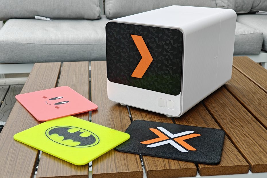
The N5 Mini: A 3D-Printed 5-Bay NAS for 3.5″ Drives. The 175x175mm answer to the Minisforum N5. Use Whatever Mini PC You Want!
First of all, can we just acknowledge the beauty that is the Minisforum N5?
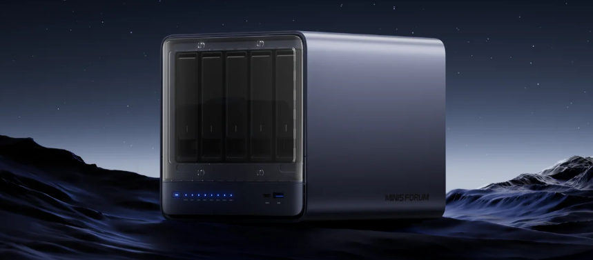
I love and adore this thing. The ($729 USD) Ryzen 7 255 packs 8 cores/16 threads, a 58-TOPS NPU and Radeon 780M for balanced home media, storage and light AI, while the ($1,299) Ryzen AI 9 HX Pro 370 brings 12 hybrid cores, ECC memory support, a 50-TOPS engine and Radeon 880M. The 255 nails everyday performance on a budget, whereas the 9 HX Pro 370 ensures headroom for heavier workloads.
It comes in these two flavors, but like, here’s the thing…
At these prices, it unfortunately really edges out the budget homelab user. Especially when put up against the notion of having to sell your current mini-pc that is potentially powering everything already…

But WAIT. What if… you could re-use the mini pc you already owned?
Riiiight? That’s what I’m saying! Let me use whatever mini-pc I want, but give me the charm and glamour that I feel with the Minisforum N5!
What were the goals of this build?
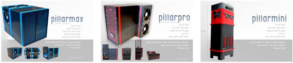
As you’ve undoubtedly noted from the previous “pillar” NAS builds, I absolutely value NOT relying on Mini-ITX. It makes builds unnecessarily large, and I don’t believe it to be power efficient enough, no matter the level of ATX power supply you find. It simply doesn’t hold a candle to a laptop-brick style power delivery system.
- GOAL 1: First and foremost, it MUST fit on the very popular Bambulabs’ A1 Mini 3D print bed at 180mm x 180mm (and goal fraught with multiple ‘oh no’ moments, but overall were triumphant!).
- GOAL 2: Secondly, it must reflect the same charms as the Minisforum N5, while relying more on “open” techniques and methods of implementation.
- GOAL 3: Sip power. Be easy to build (by requiring NO supports for the main large pieces).
And… that’s basically it. Pretty simple (but a large goal, to be fair).
How was this designed?
The design is from scratch, done entirely in Shapr3D. In my day to day life, I work at a university, so, having access to Shapr3D via their EDU affiliation is a massive perk for me.
Is the print complex? What pieces are there?
Easy.
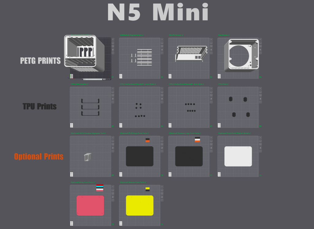
In either Orcaslicer or Bambulab studio, you’ll notice the simplistic nature of this release. The top row of items are required PETG prints. The TPU prints are pretty important – I haven’t tried printing any of them in harder material, but I think TPU suits the need best for them. If you’ve never printed in TPU, don’t be scared – if your print head uses direct drive extrusion (as many do now) its quite simple — I encourage you to give it a shot.
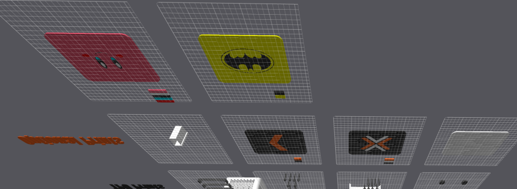
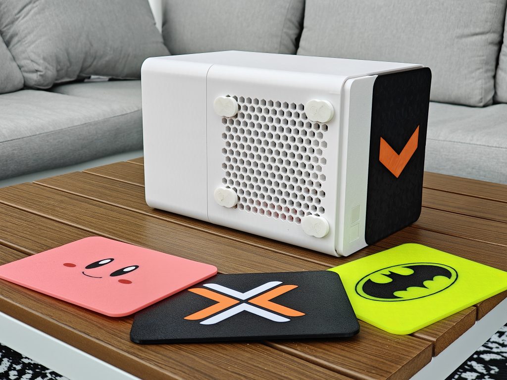
The bottom rows are optional. Most of them are the included faceplates I’ve made:
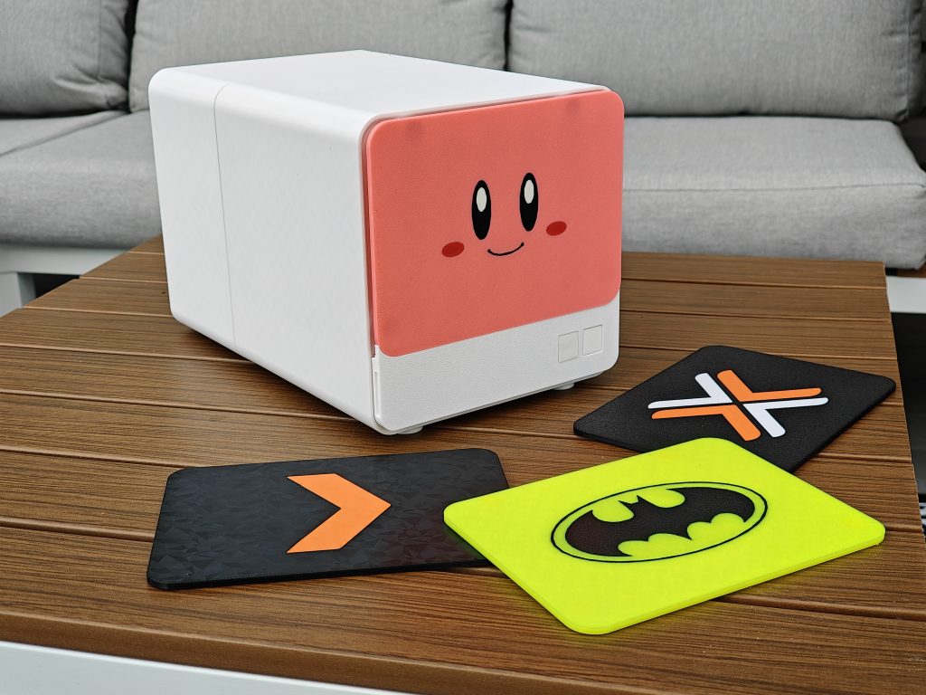
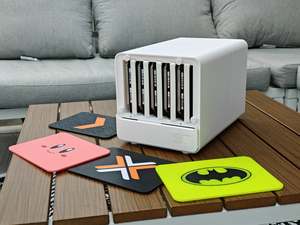
Oh yes, and a bonus feature I noticed after the fact:
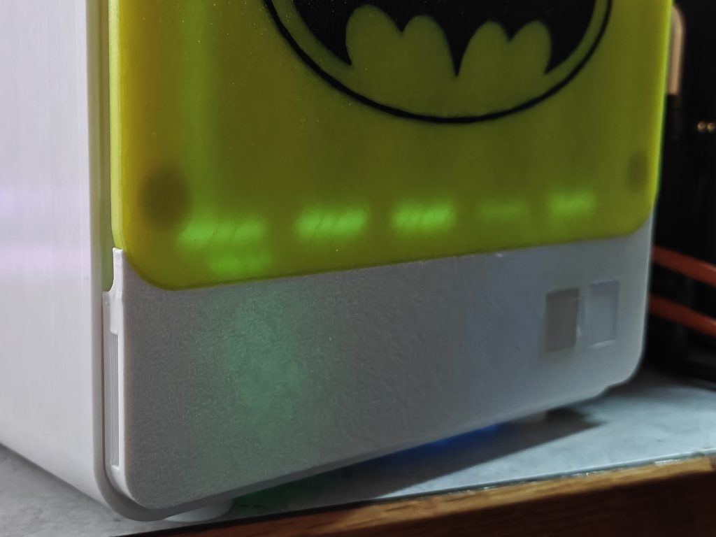
If you print with something with a little lighter color or lower transparency, you’ll see the “thinking” lights of each hard drive shining from clear in the back of the backplane holding the drives in place. This one is glow in the dark.
Yes yes, great, whatever – make with the build plans already.
Right, yes, of course. Right away. Here’s your instructions for the build: (Bolded parts are the cliff notes if you’re feeling confident). Parts list is at the bottom of this post.
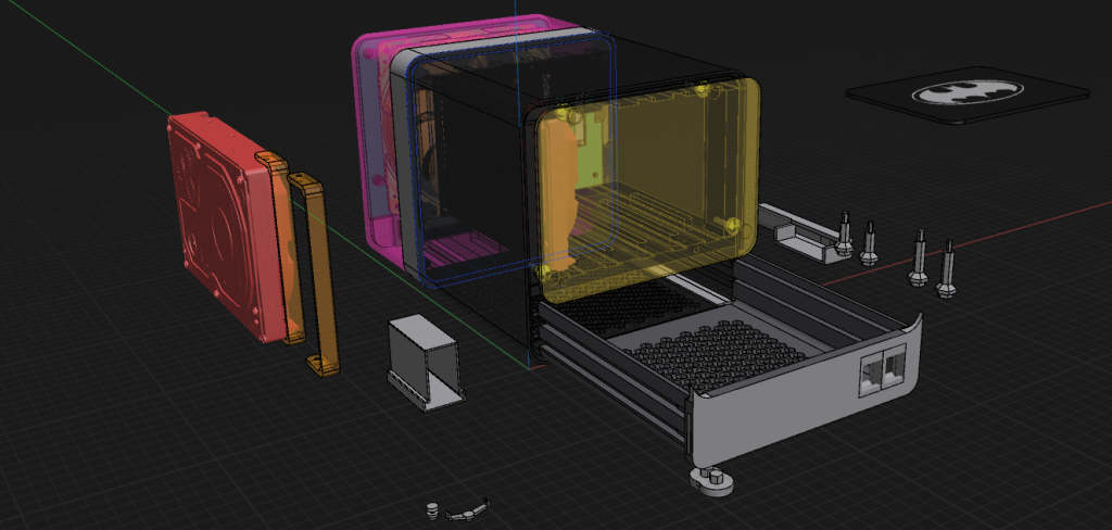
The Hard Drive Bay Zone:
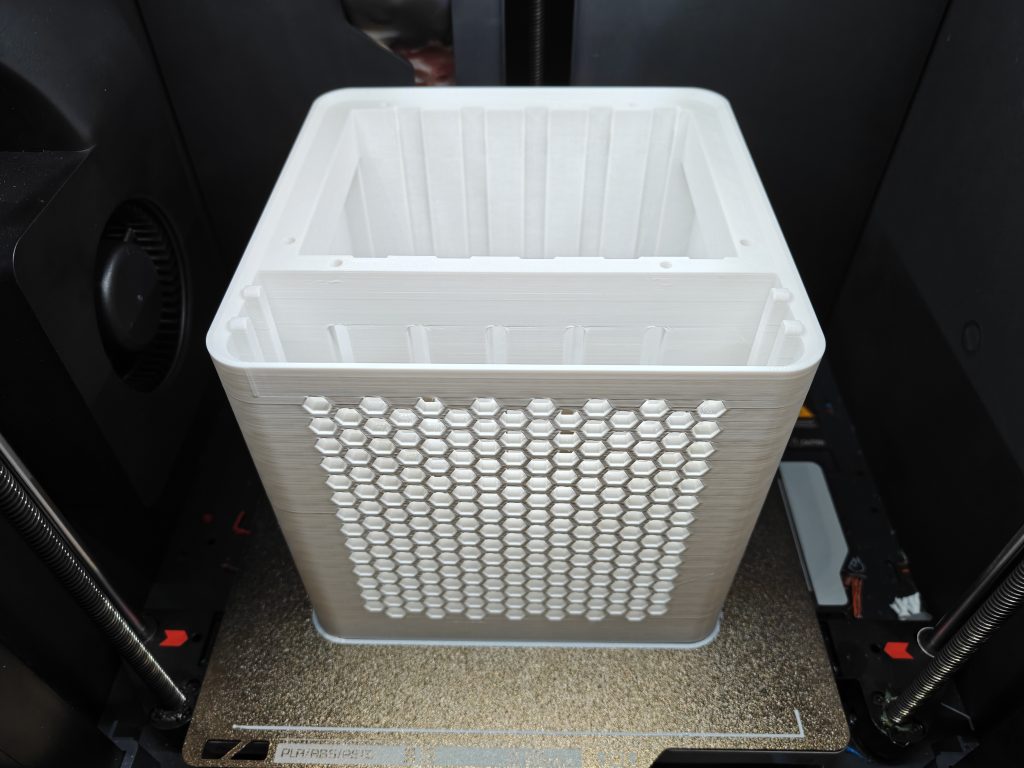
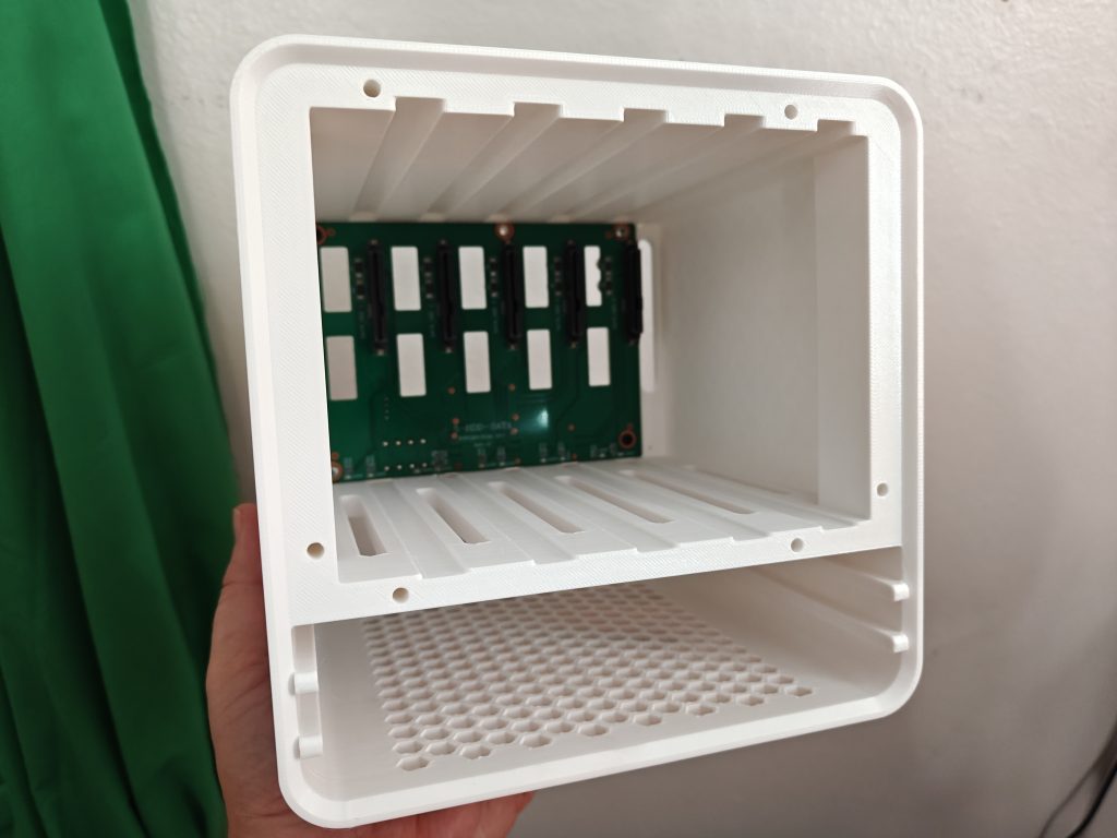

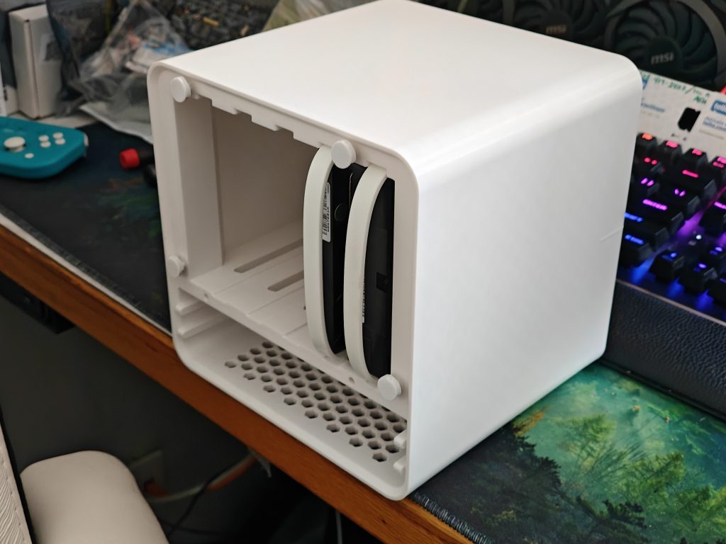
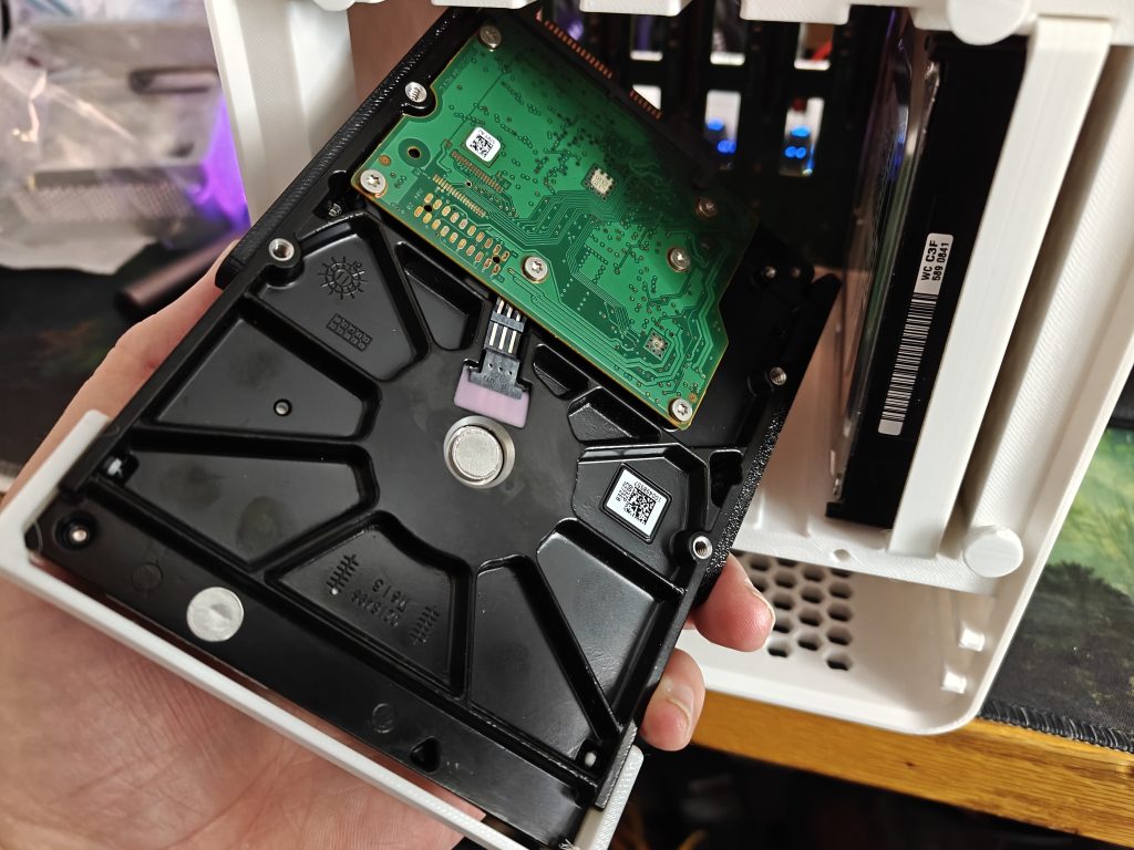
Image gallery mode here should help us consolidate the images better while I explain a bit (sorry anyone reading this outside of jackharvest.com).
Print the main body out of PETG (you might get away with PLA, but come on, these put out some warmth and over time, you don’t want some soggy mess to discover). I was honestly going to go with black, but, after my test prints were coming out clean, I just kind of… kept going with it. xD
Install the 5-bay backplane PCB using M3 screws. Short ones are great (I used some PC screws I had laying around — the kind for motherboards or hard drives work fine). I installed the top left and bottom right screws first, ensuring they were as centered as possible. It just has to be close. I didn’t bother to put in a 5th screw, despite the board allowing for one.
Test the fit. Slide a drive or two in to ensure the SATA ports line up.
Print the magnetic faceplate grabbers. Pinch the 10mm x 1.7mm magnet into the half slot gently. Insert them into the front of the hard drive bay zone holes. (Top two holes, and outer most holes; Ignore the holes at the bottom of the opening).
The Mini PC Drawer Zone
Pull the motherboard out of your Mini PC (Youtube is your friend, they aren’t difficult).
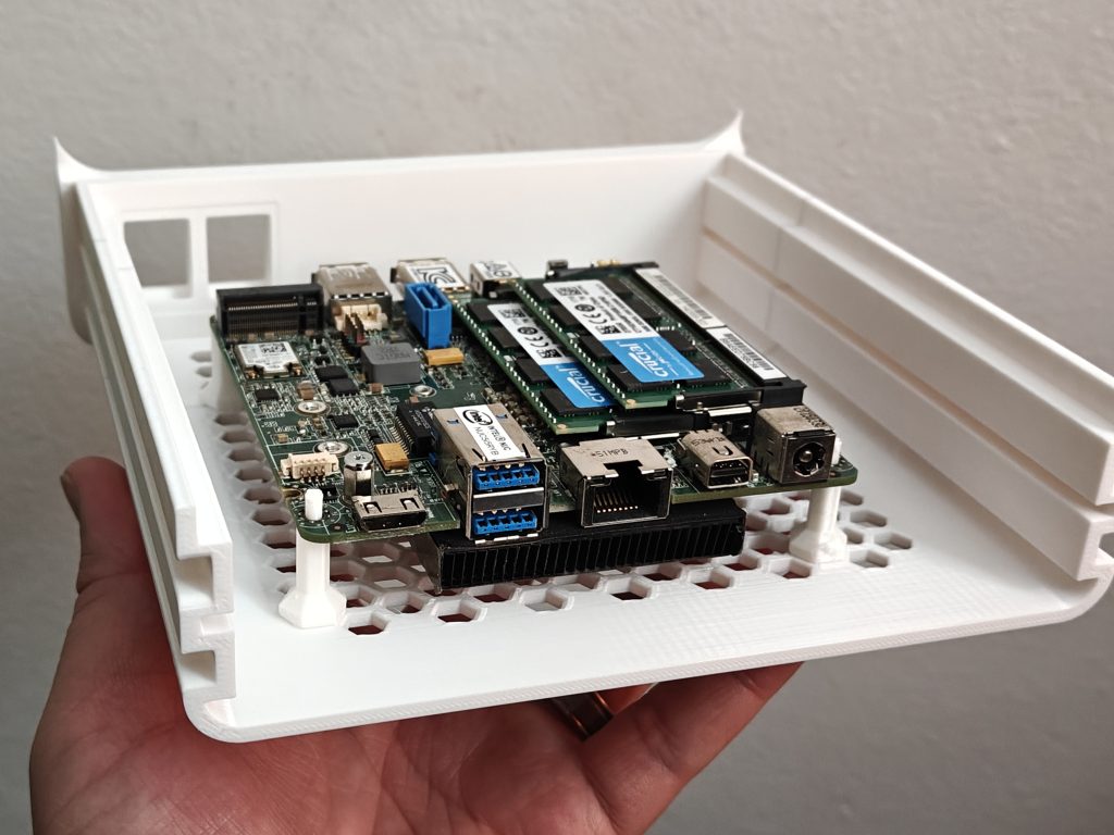
I highly recommend using a smaller board in here, with a 4×4 footprint. Most Mini PC devices from 2015 forward fit this nicely. Pictured above is an Intel NUC 5i5 from 2015. Don’t go older than this, as M.2 PCIE slots for SSDs and such weren’t really standard prior to that, and straight up non-existent on Celeron or Pentium builds.
Print the TPU motherboard offsets, and mount them into a hexagon vent hole of your choosing. I’d recommend keeping some space on one of the sides. You’ll see why later (and it probably wont be the same side that I chose).
Pop your motherboard onto the mounts.
Confession: I used the wrong sized motherboard from a Minisforum NAB6 (5″ x 5″), and the rest of my screenshots show that poor thing crammed into this drawer. Just know yours will breathe easier. xD
Still with me? Easy so far. Let’s work on the butt power section.
Just put it all together and close the lid. And you’re done!
.
.
.
.
.
.
Shhhh! Shhhh! …are they still out there reading the post?

.
.
.
.
.
.
I’m kidding of course. This isn’t one of those tutorials. First, lets view the gallery, then, lets step through the gallery slowly.
Caution: Do NOT freak out at the next images. We’re going to talk through these steps slowly. The gallery is just here for people rushing through this build haphazardly. We’ll highlight and slow down, and make sure this is like electrical instructions from Fisher Price.

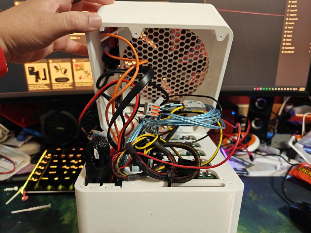
The… actual power section. Nice and slow. This is EASY, just follow along.

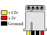
Just like this absolute turd of an AI generated image shows, your Mini PC wants 19V to run. Your hard drives need both 12V (to spin) and 5V (for the green board on the bottom).
The most economical way to approach this, without needing hardly any space at all on the inside, was to use two power cables. Some will be disappointed by this approach, as all the Pillar NAS builds featured a singular plug. But, the larger the voltage, the larger the buck converter, so, our best approach was to just direct-feed the 19V to the Mini-PC, and have the 12V plug convert down to 5V on the inside (while still using the 12V as well, of course).
If your Mini-PC is compatible with 12V input (and some are, despite it coming with a 19V wall wart), you can likely power the entire unit from a singular cable, and just feed the mini-pc (as long as its amperage demands are meager).
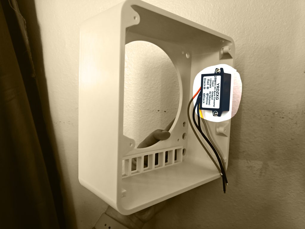
Power Step 1: Install the 12V/24V –> 5V downstepper using two screws (M3 / PC screws).
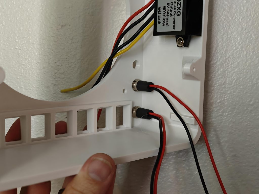
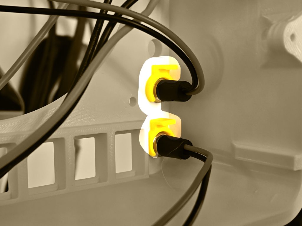
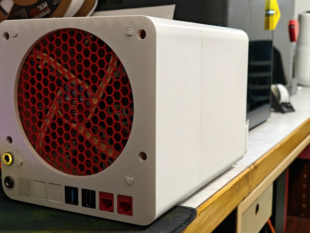
Power Step 2: Install the two DC barrel jack connectors.
The connection should be a perfect “screw-in” fit.
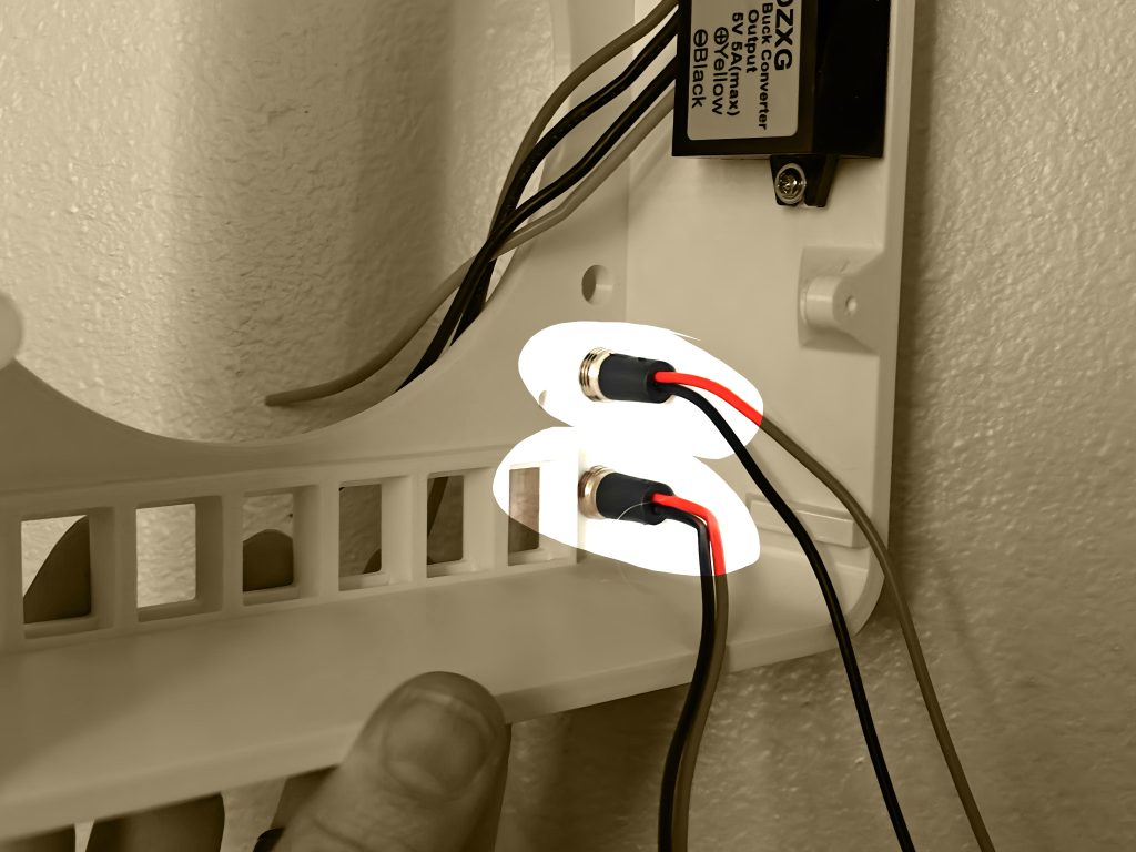
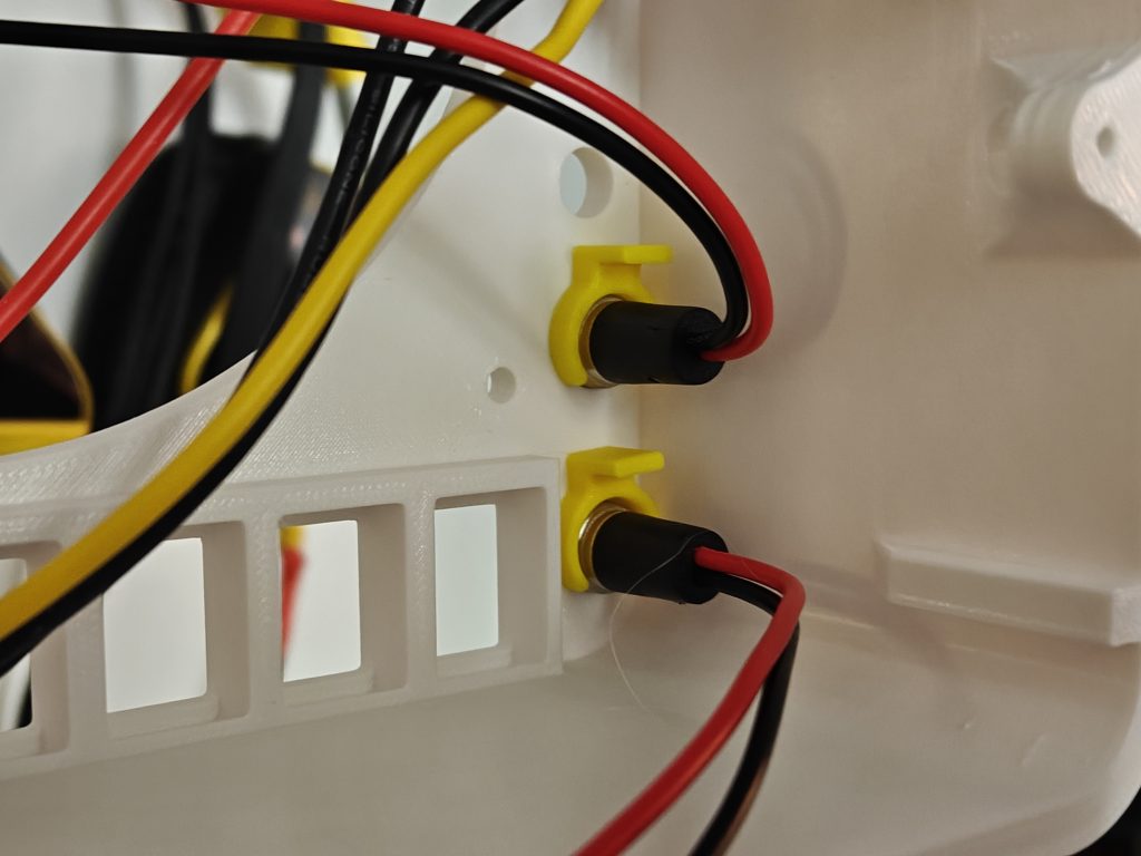
If your tolerances are wonky, you can use the snap-clips (see below); There isn’t enough space in this build to accommodate the locking nut these came with.
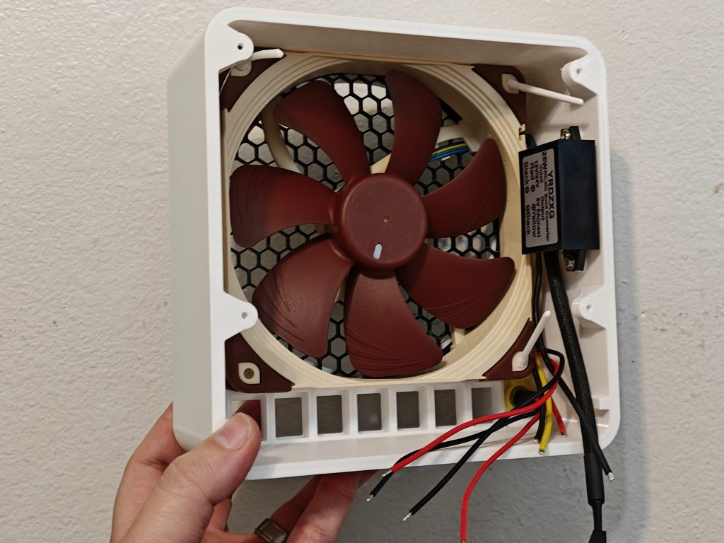
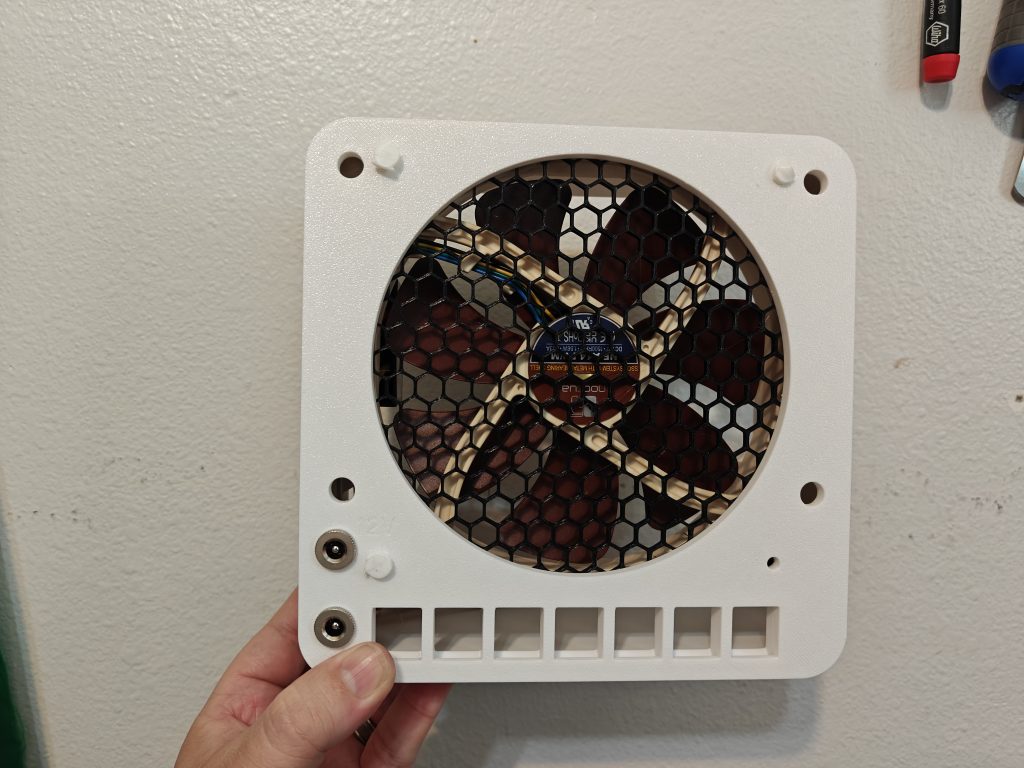
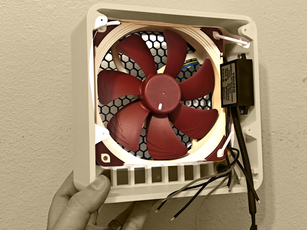
Power Step 3: Install the single 140mm fan using pull-through TPU fan screws. Remember to put your hex grate underneath it.
The hex grate underneath here should be 2mm thick. Add another hex grate (NOT PICTURED) on this side of the fan as well (recommended 4mm thickness). Failure to follow these thicknesses will mean it wont fit properly; You want the thicker one near all the cabling to help it not flex into the fan.
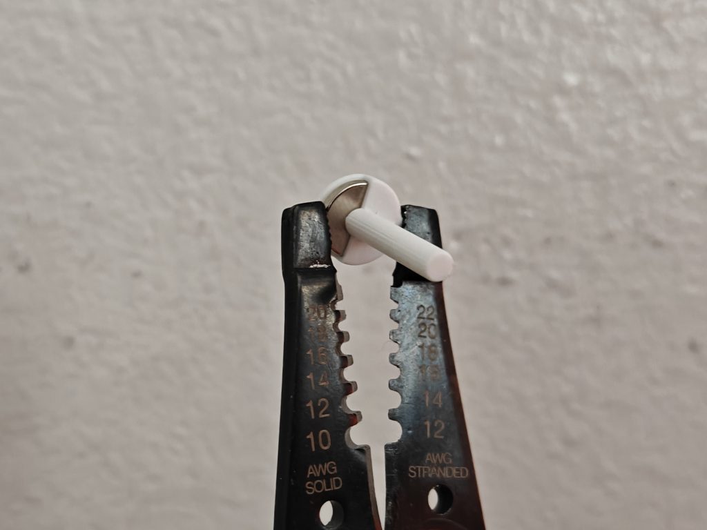
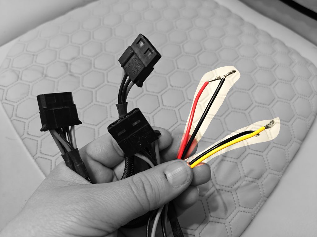
Power Step 4: Use a wire stripper or pocket knife to make all those loose cables exposed by the length shown on the bottom of your lever lock nuts (read: I hate soldering, Fisher Price electrical for babies on EZ mode)
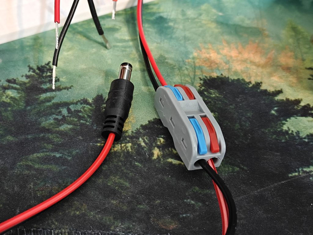
19V Power Step 1: Lets do your Mini PC 19V plug first. (The 19V is the bottom barrel plug).
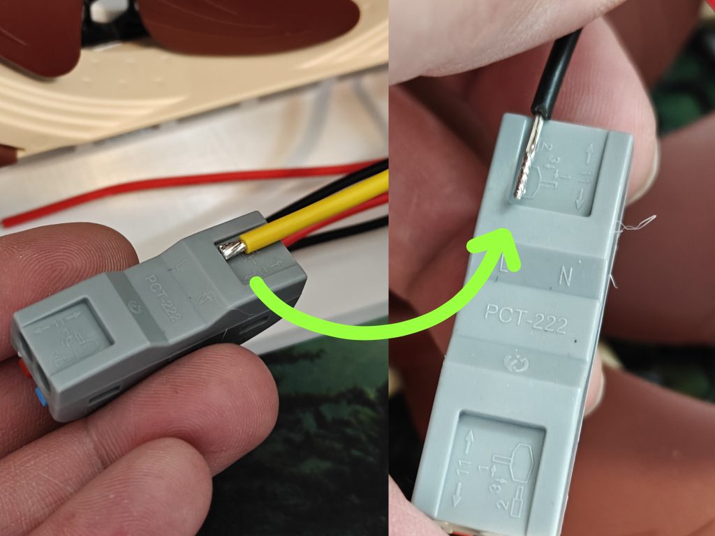
Open the lever lock, push the wire in to the proper colors (Red to Red, Black to Blue). (Two completely separate lever locks is acceptable here if you don’t have a dual-passthrough style one as shown below; (One for + (red) and one for – (black))
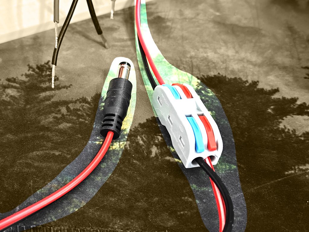
One the other side, insert your included DC Plug to red/black wires.
You did it. 19V is complete. Pffffft, easy.
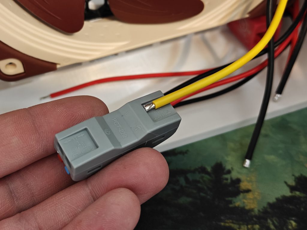
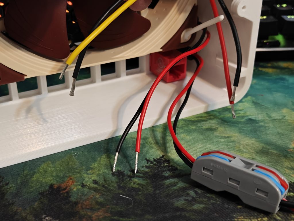
12V Power Step 1:
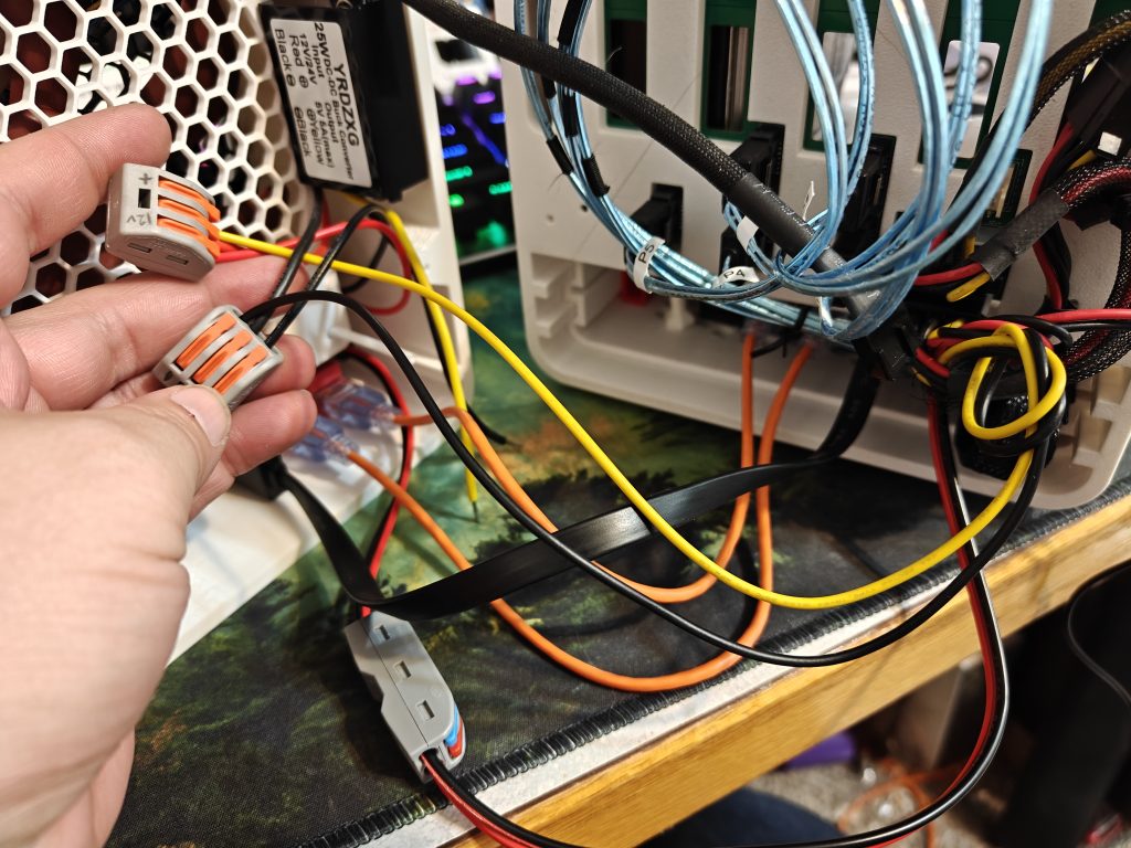
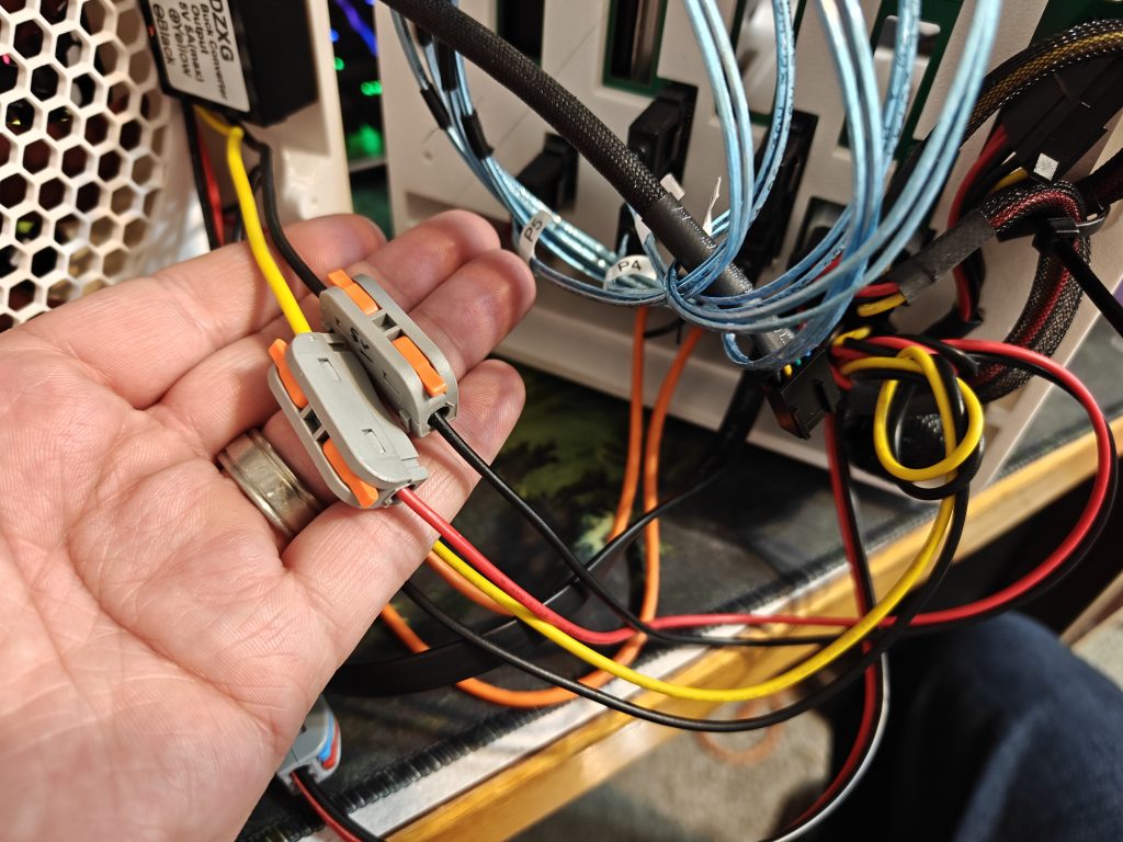
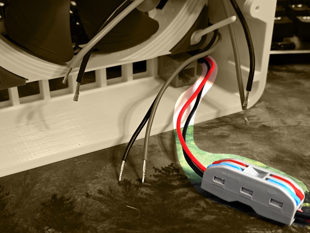
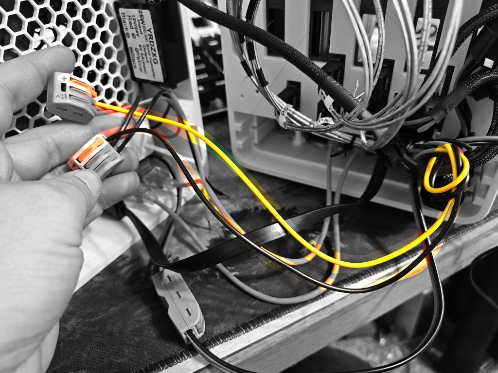
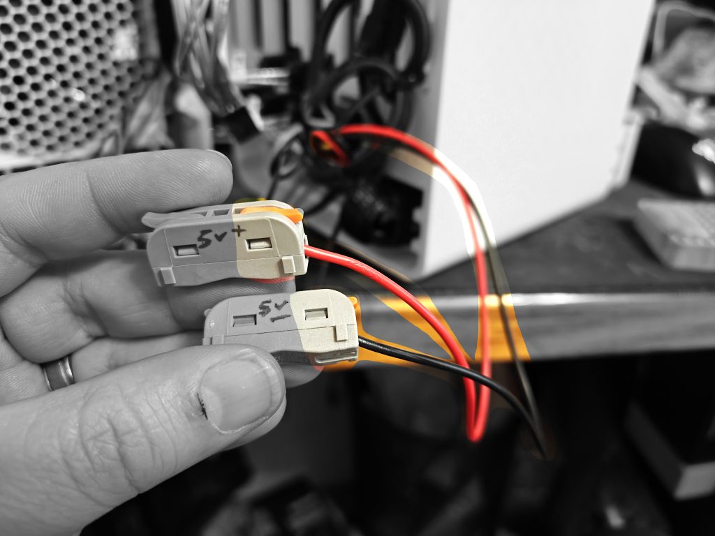
A few things need 12V. So, spread the love with this multi-connection lever lock nut. Mark one as 12V + and 12V – to help you easily keep track. Our black wires will go in one, and our red wires in the other. Easy. Plug in the two colors from the 12V input barrel jack plug (top one).
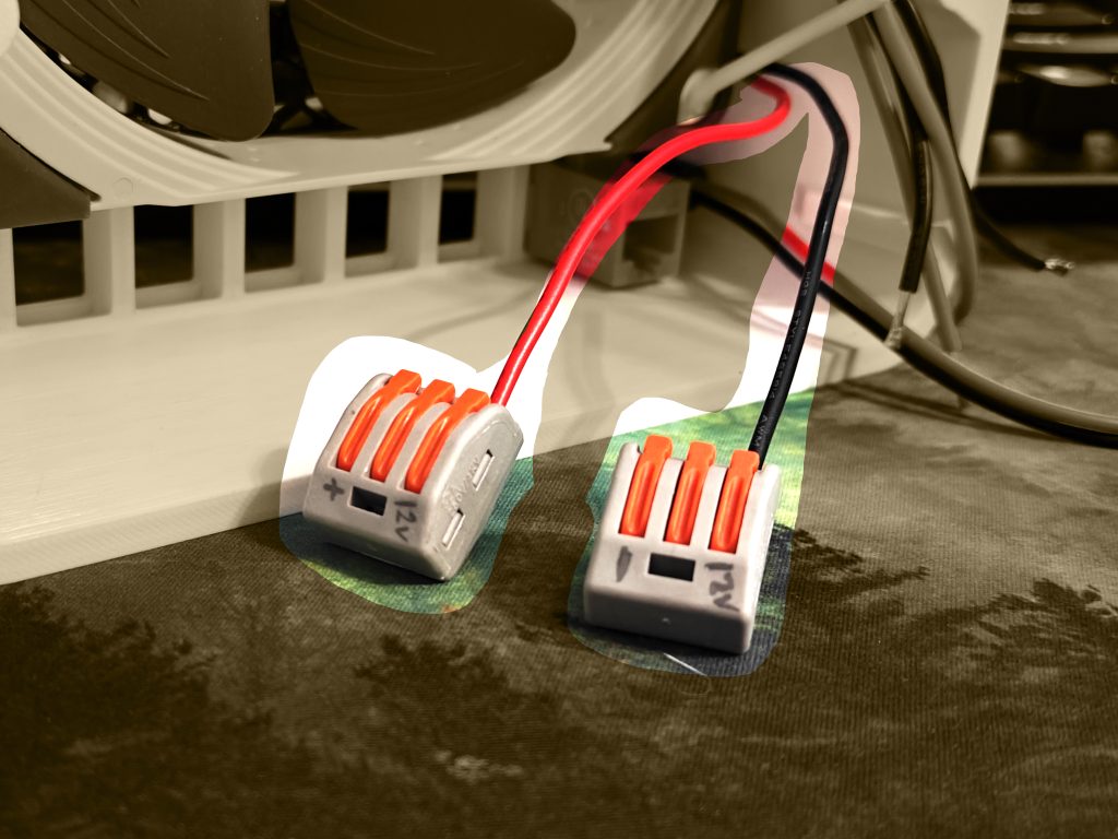
12V Power Step 2: Give some 12V love to that downstepper you hung on the wall so nicely.
(These two wires come down from that 12v to 5v downstepper). Double check that your 12V is red and black on that downstepper, mine was, but yours may be reversed. Don’t trust colors, trust the label.
12V Power Step 3: There’s only one thing left that needs 12V — your hard drives.
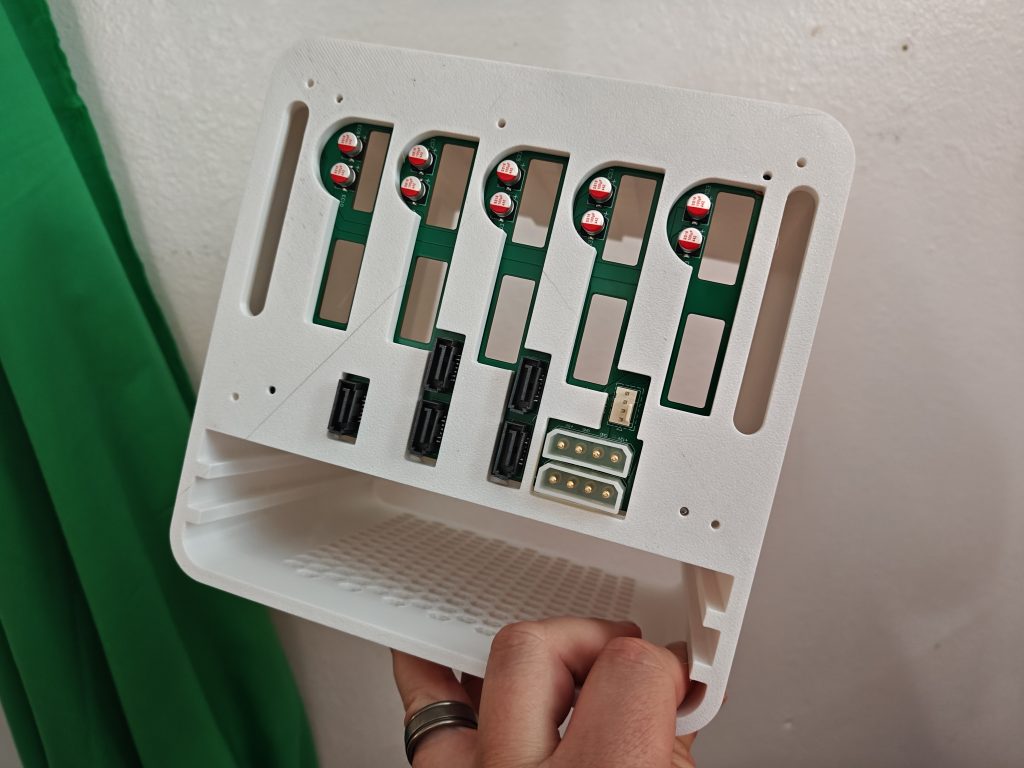
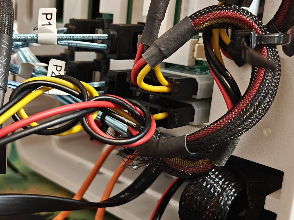
See those two white trapezoid connectors there? That’s colloquially known as Molex. They power all your drives, as well as the little fan power connector there.
So, as per the diagram here, we’re looking at “12V+” as the far RIGHT one on our backplane there, and the far LEFT one is “5V+”. The “-” of each one (12V- and 5V-) are next to their counterparts. Actually. Its confusing. This stupid infographic… you have to basically turn it 3D, put it in your hands, and pretend you’re plugging it in. Lets make it easier.
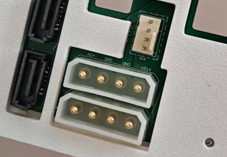
Here, this is less confusing. There are literal LABELS on the back of your PCB here. And, with the trapezoid shape, you can’t screw up the way you plug it in. So, follow the cables, and you’ll be golden.
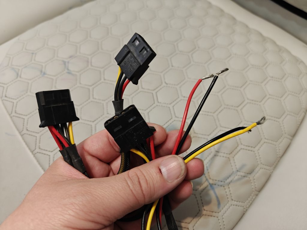
On your multi-molex adapter you have, you’ve followed the cables, then cut off whatever end it used to have, and have confirmed you have some 12V, and some 5V. Nice. Again, 12V makes the drives spin, 5V is what the little motherboard on that hard drive runs on. Easy.
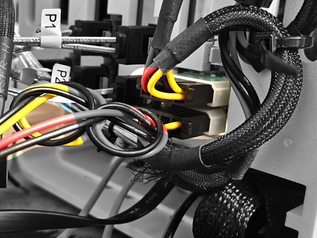
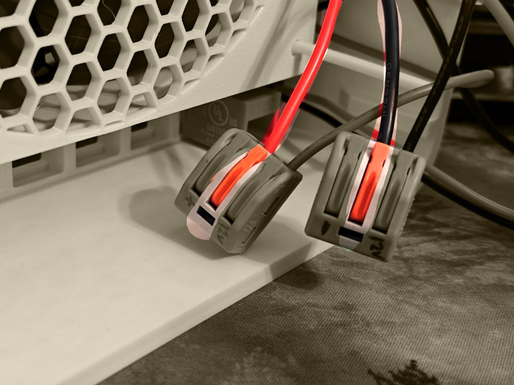
Nice and easy now. Just plug in two of your molex here. That’s it. I know the picture looks crazy, but seriously, we’re just plugging those two in. Note the yellow/black and red/black cables that come off it. (Yours may be all black, which you’ll just have to keep track of based on the trapezoid plug and the PCB label.
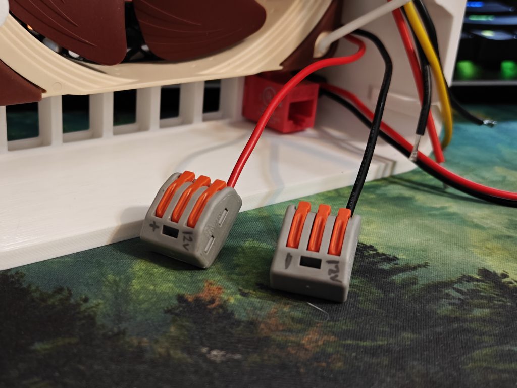
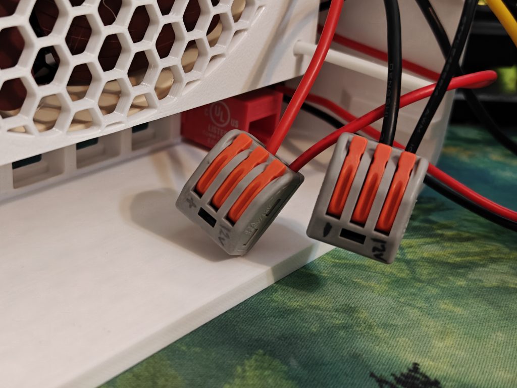
12V Power Final Step: Plug the 12V + and – lines from the molex connectors, and land them in the final spot on your lever lock nuts for 12V + and -, respectively.
*PHEW*. So that’s 19V and 12V all out of the way. Just 5V left, and its only used in one place!
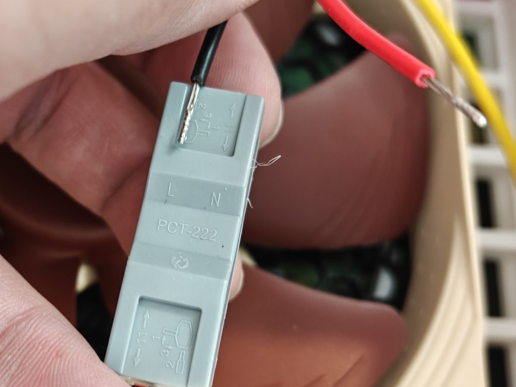
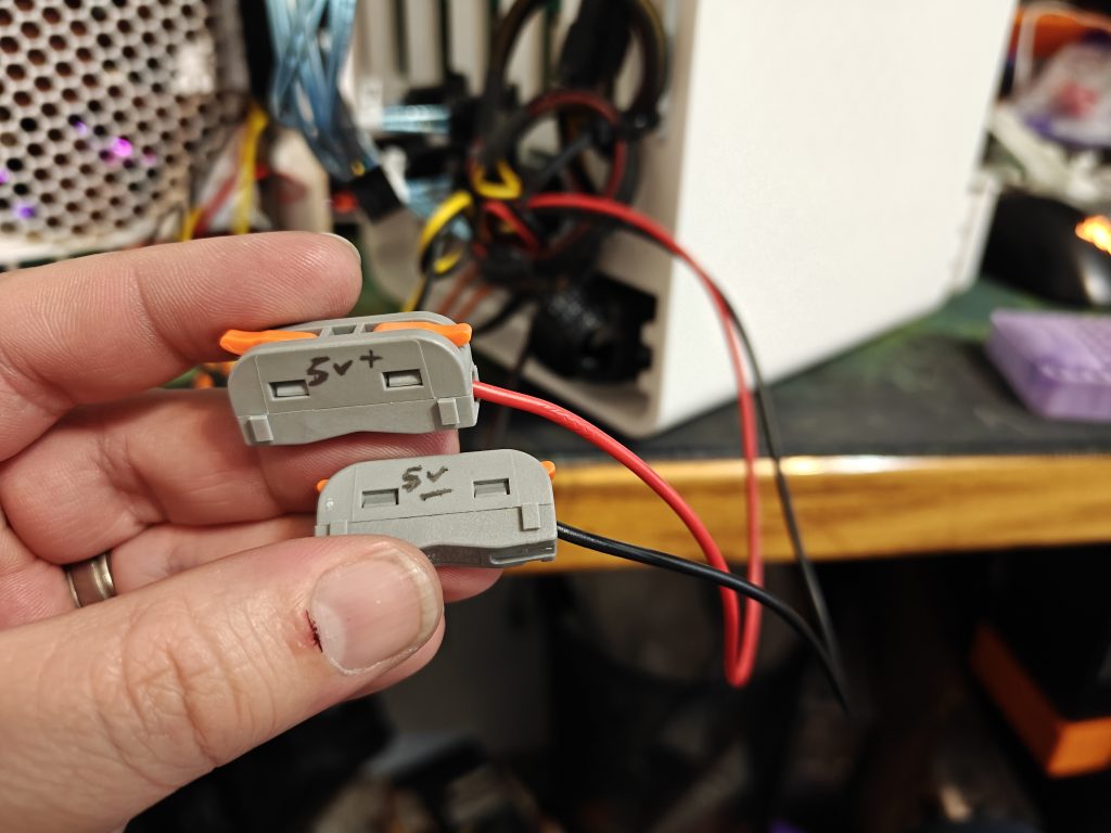
5V Power Step 1: Using just little singles, connect from the molex adapter the 5V lines…
And finally land that with the 5V coming out of the downstepper.

FIN. You did it. You’re basically an electrician now. WOW. I’m so impressed with you. Give yourself a round of applause. Too much? Alright, an octagon of applause then, whatever.
Connect the fun stuff.
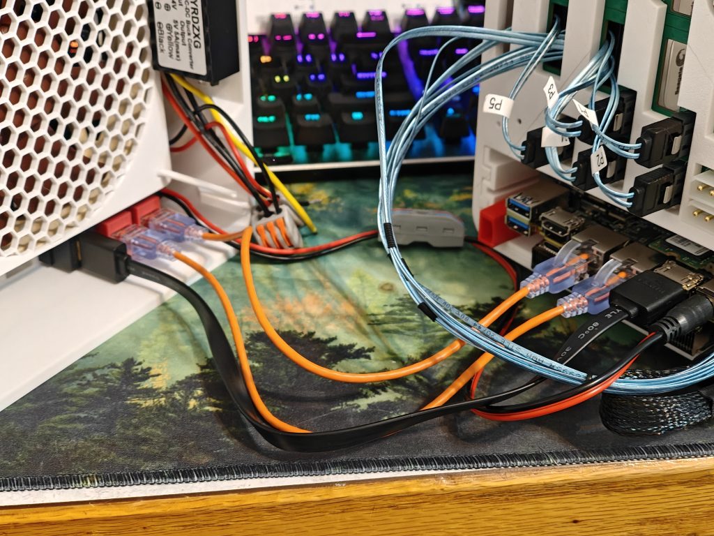
Plug in your keystone jacks that you’ve opted to install. Ethernet and USB are recommended. I added HDMI, but I probably could have gotten away without it if I’d set up my OS in advance. Plug your SATA plugs in that come off your Sata adapter.
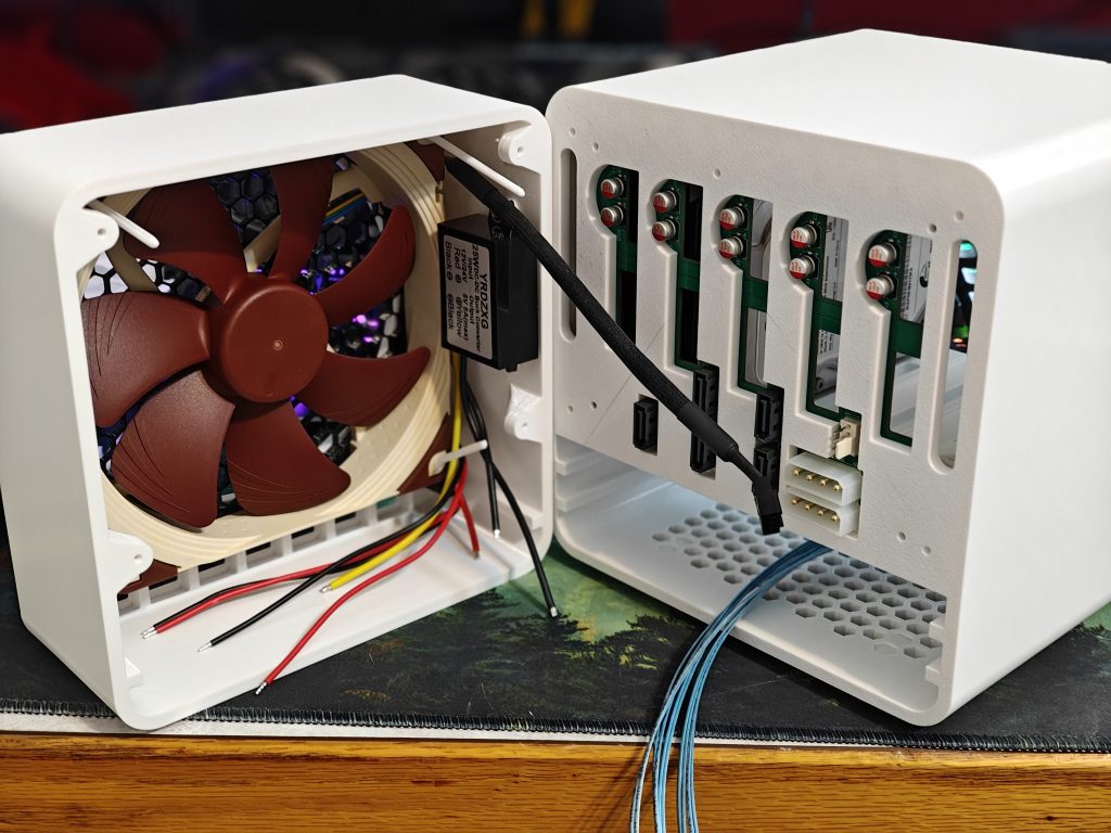
Oh wait right, the sata adapter. We need to talk about that still!
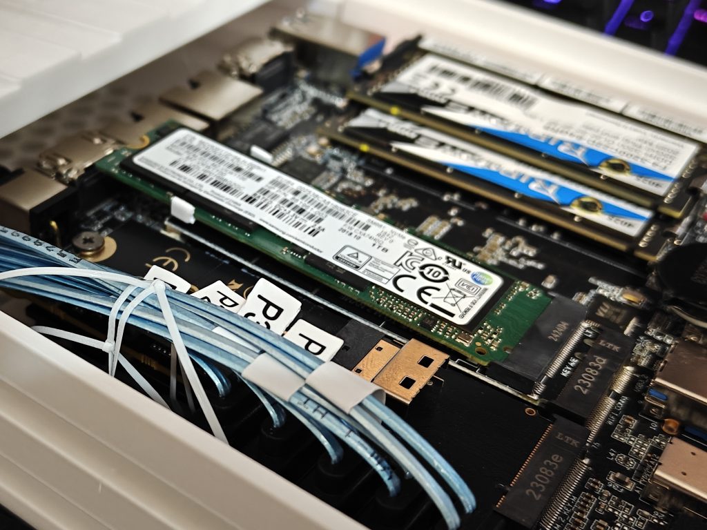
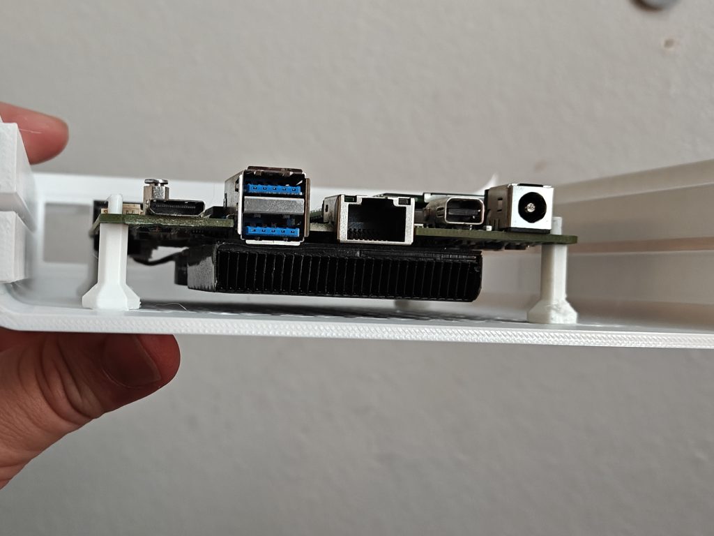
Again, your motherboard wont be squeezing in here (unless you’re crazy like me an just tossed a 5 inch board in here without standoffs hoping for the best) so don’t feel claustrophobic by the image, but, your M.2 SATA port adapter sits on the side next to your motherboard. It’s LONG so it really couldn’t go anywhere else or else the “drawer” functionality would start to get funky.
(And you’re seeing that right; The NAB6 had a wifi card in the middle, and I shoved an E-key to m.2 nvme adapter in there, and used a mild riser for the SSD to clear the HDMI port in back… look, put the OS on whatever you can, right? My proxmox didn’t want to live on a USB stick, but it absolutely could have… You do you. Obviously something with 2 normal M.2 ports is ideal here.)
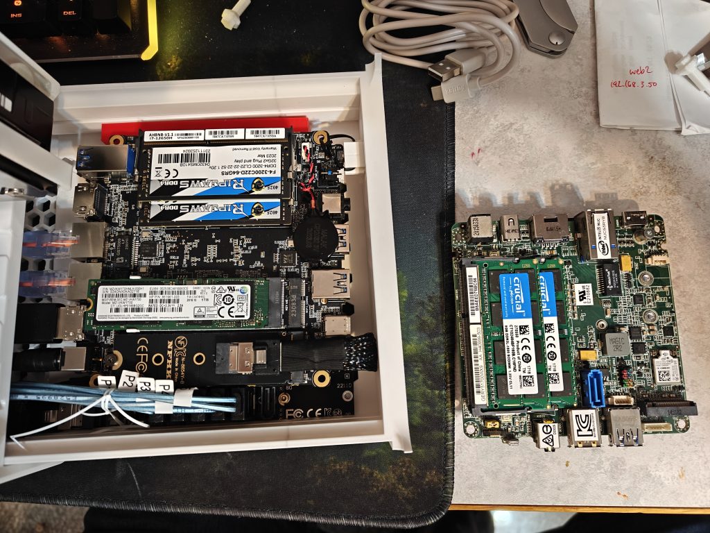
See? The 5 inch board vs the 4 inch board.
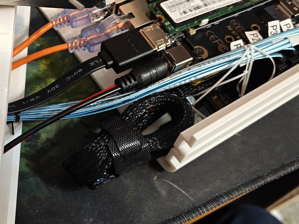
This cable that connects the M.2 port and your SATA ports adapter really wanted to live in a desktop or something. The cable is a little longer and stiffer than I thought it was gonna be 😏, so, a solid velcro job is really gonna help here.

See? Not so scary now. Cable manage the best you can; We’re screwing this part shut, so as long as the drawer isn’t gonna fight anything too much, we’re good. Airflow is awesome in this thing, so the cables are just gonna cable, and that’s fine.
As you go to screw it closed (with, ahem, more M3 screws… these ones being a little longer than typical PC screws. I can’t remember the length I used, but you really have a range to work with here. 10mm to 14 or 16mm will suffice if I’m not mistaken) I HIGHLY recommend you half screw them in them while the thing is open. Otherwise you’ll be playing a very scary game of “don’t drop the mildly magnetic screw” as you balance it in the hole.
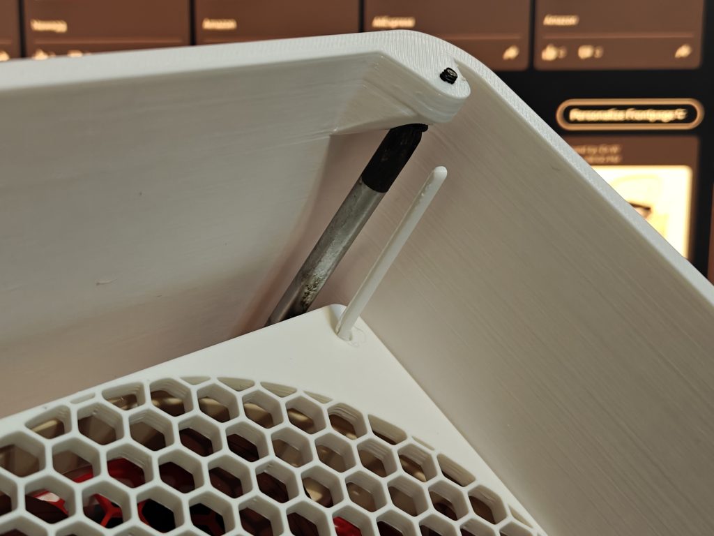
That’s the only function for these holes on the back; They line up perfectly so you can put a screwdriver through it easily:
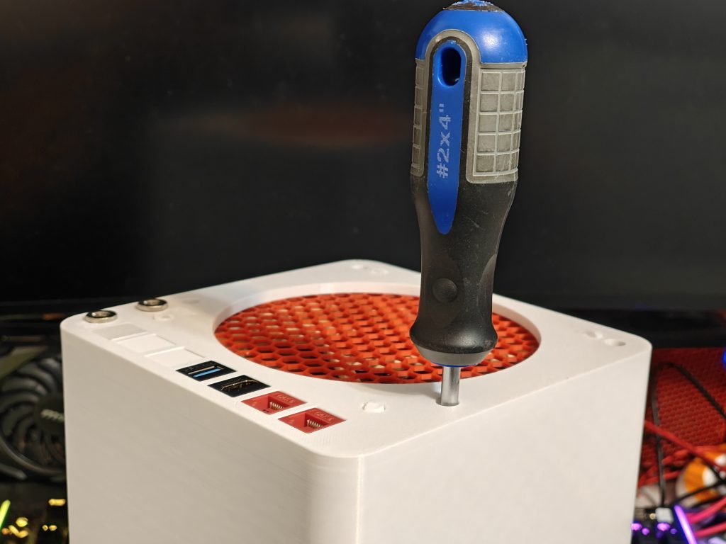
I found it easiest to finish the job with the whole thing lying on its face. No need to tighten too crazy.

I’ll be honest, I printed probably the better part of 6 drawers getting the “grab” just right so it would pressure fit just perfectly near the “end” when the drawer is almost closed. Added indents to ensure it was easier to pull out. Added rounded corners where relevant so the magnetic faceplate would glide into place instead of snag… there were a lot of fun little quirks that really pushed me to get it just right before public debut.
Oh yes, print and attach the TPU feet. They plug right into the vent hexagons on the bottom. No feet are needed on the rear portion, as 90% of the weight is in the front portion.
Ok yeah nice, so, instead of $720 for the perfect one from Minisforum, what am I throwing down for this bad boy?
Yes, right. Cost breakdown. This is probably easiest ingested as a table chart from Google sheets, so, here goes nothing: (I’m making some assumptions on you having pretty much nothing going into this except your 3D printer and some hopes and dreams — mostly)
| Description | URL | Qty | Unit price | Total price |
| 5-bay Backplane | Link | 1 | $16.95 | $16.95 |
| 10mm x 2mm Magnets (30pk) | Link | 1 | $5.99 | $5.99 |
| Your Mini PC of choice. (The guide assumes you have one – anything with at least one NVME slot should work) | 1 | $0.00 | $0.00 | |
| 5.5 x 2.5 MM DC Power Jack Socket (Male + Female) | Link | 1 | $8.99 | $8.99 |
| 12V/24V to 5V 5A 25W Buck Converter | Link | 1 | 9.99 | $9.99 |
| 32Pcs Lever Wire Connectors (For no-solder approach) | Link | 1 | $14.98 | $14.98 |
| Noctua NF-A14 PWM, Premium Quiet Fan, 4-Pin (140mm, Brown) | Link | 1 | $25.00 | $25.00 |
| 5 Pack of Thin SATA Cables | Link | 1 | $9.99 | $9.99 |
| 10 Pack of Thin CAT6A patch cables (1FT) | Link | 1 | $10.39 | $10.39 |
| 2 Pack of USB 3.0 A to A | Link | 1 | $8.99 | $8.99 |
| 5 Pack of CAT6 RJ45 Ethernet Keystone Jacks | Link | 1 | $6.99 | $6.99 |
| 6 Pack of USB 3.0 Keystone Jacks | Link | 1 | $8.99 | $8.99 |
| Multi-Molex Power Adapter (That you’re going to snip the proprietary end off of) | Link | 1 | $11.99 | $11.99 |
| M.2 to SATA3.0 Adapter Card, 6Gbps High Speed ASM1166 M.2 M EKY PCIE3.0 to SATA Expansion Card Adapter | Link | 1 | $31.32 | $31.32 |
| Keystone Blanks (just 3D print these) | $0.00 | |||
| M.2 NVME NGFF M-Key Extension Cable 40cm 2280/22110 (We need this because the drawer is so thin we cannot dream of plugging in the sata plugs on top of the motherboard) | Link | 1 | 26.88 | $26.88 |
| Making an assumption you have M3 screws. | $0.00 | |||
| 12v 10A Power Supply [Brick Outside Box] | Link | 1 | $17.99 | $17.99 |
| 19v XXA Power Supply for Mini PC (This… came with your mini pc, just use it) | ||||
| Notes: If links go dead, just google the description and check the images to ensure its the same. | Subtotal | $215.43 | ||
| Adjustments | $0.00 | |||
| Pretax | $215.43 | |||
I absolutely hate listing all that out. I definitely had half of it from previous projects (I swear!). This cost DOESN’T include the mini PC itself, as we’re making a general assumption that you’re going to put something inside that fills your needs (an N100 with no guts to easily run Xpenology via proxmox on 6w of power? An AMD Ryzen board with 96GB ram and a billion VMs and containers? The number of options in between is vast).
So, if you’re tossing in a $40 Intel NUC 6th gen from ebay, a stick of memory and you’re running your hypervisor off a jump drive, sure, I’d wager you’d easily slide in at under $300, realistically.
I mean a 5-bay Synology is nearly $800 USD, so, to make your own N5, it really is exceptionally palatable, all things considered.
Enough about money, where do I download the goods?!
I’m hosting these on Makerworld. I know, I know. I enjoy pushing these out for free, so, a boost here and there on Makerworld really goes a long way for me. About 200 hours went into the design. 😀 I’ll publish the raw Shapr3D files after a month or two of release, just as I’ve made the Pillar series open source.
Please enjoy. I’ve bought so many Minisforum machines… I just wish the N5 would have had a budget processor option.
Would a motherboard from a hp elitedesk 800 g5 fit?
It does not. I assumed it would but the motherboard is far too big. I wish I checked before getting all the parts and assembling. Lesson learned lol. Now I need to pick up a new mini pc.
I love this! I have been wracking my brain trying to figure out how to power several 3.5″ hard drives and a mini pc at the same time to make a compact NAS. I haven’t purchased a mini PC yet as I am looking for something in particular. I don’t need the case you made, but I really want to remix this to fit in my 10″ Lab Rax Rack. The question I have is, when you shut your NAS down, does EVERYTHING power off at the same time? If not, that’s really what I’ve been wrestling with. My idea is a Step down/Boot converter with one input that would support the 19v for the mini PC and at least three outputs controlled by potentiometers so you can dial in 19v, 12v and 5v. Not sure if something like this exists and I’m not sure how much Amperage would be needed for the whole thing. If someone knows about something like this, please share.
I don’t usually comment on random blog posts Google recommends to me, but you’ve done a great job with this!
I’ve had a similar plan in mind for a while now and this is the inspiration I need to give it a go!
Thanks for sharing 😀
This looks so good. I wanted to something similar with a 3x 5.25″ HDD enclosure instead. Ideally with a 4th Slot for a BluRay Drive. Sadly my 3D Design skills are not there yet but maybe when you release the files I can look into modifying this base and design it to house a RK3588 ARM based SBC with 2.5GbE
I literally just finished designing a 5 in 3 hot swap bay using this same PCB actually. Very similar designs overall but different goals (to be put in a silverstone rack chassis). I managed to get it to work with a front fan and should have decent airflow. I’ll probably have it up on thingiverse later this week, the final version is actually printing right now!
I really like this. Thank you for your work.
Unfortunately the backplane is hard to come by in germany.
I did some research on the backplane and think it is the same layout as the backplane for the Jonsbo N1/N2 case.
Jonsbo does not provide spare parts to buy online, but you can contact the Jonsbo support via email. The spare part cost 32 USD including international express shipping. Unfortunately this does not seem to be a viable option when you want to build multiple systems for all family members.
Awesome!
This is phenomenal!
Props for an incredibly well executed design. I’ve wanted to build a mini PC+M.2-SATA NAS for at least 6 years, but always shelved the idea, primarily because of the power supply problems and the complete lack of fabrication skills.
Now that I have 3D Printer friends and a conveniently provided set of plans, I can stop making excuses and pull the trigger on that NUC11TNBi5 board that perfectly meets my needs!
Speaking of, I’d really like to find room for a 2.5″ drive to squeeze an SSD cache into the build if possible… Is there room in the tray?
You mention a hex grate for both sides of the fan, but where does that come from? It’s not in the 3mf at all.
I second the call for hex grate info.
Also, if I wanted to use something like this (https://www.ebay.com/itm/256883473337) with a 12V power supply, what changes would you recommend?
Succesfully built it though with some hurdles. I was wondering if there is any way to regulate the RPM of the fan.
Is it necessary to connect the ground of the 12V power supply to the 19V supplying the NUC?
Just curios what your power drawl in watts is? I’d like to do similar with 1 3.5 hdd, 2-3 nvme, 1 sata
This is already incredible. Hope you can figure out how to make that last sata port work for a 6th 3.5 drive.