The older I get, the less I fall in love with the rack mounted monsters I once started with. Perhaps you have also set out on a quest to accomplish some of the same bullet points as I have:
Requirements.
- Must sip power.
- Must be economical.
- Must be quiet.
- Must be cool.
- Must be easy to print & build.
If you’ve done a google search recently for “3d printed NAS” you’ll likely come across several like these:


Etc etc etc.
All of these are engineering feats, and awesome in their own right, but they each suffer from varying things that we’re trying to avoid, right?:
- ??? Must sip power.
- ??? Must be economical.
- ??? Must be quiet.
- ??? Must be cool.
- ??? Must be easy to print & build.
Now, they don’t ALL miss the marks, but, many of these are no longer maintained (or got too popular and they paywalled it), are too loud, and ALL of them (except for the pi ones) require a print bed that is larger than what something small like a Bambulabs A1 mini can print (180 x 180 x 180 print bed). But most importantly…
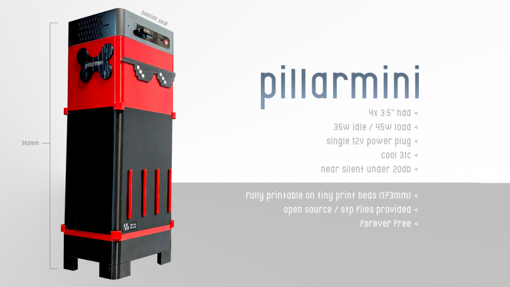
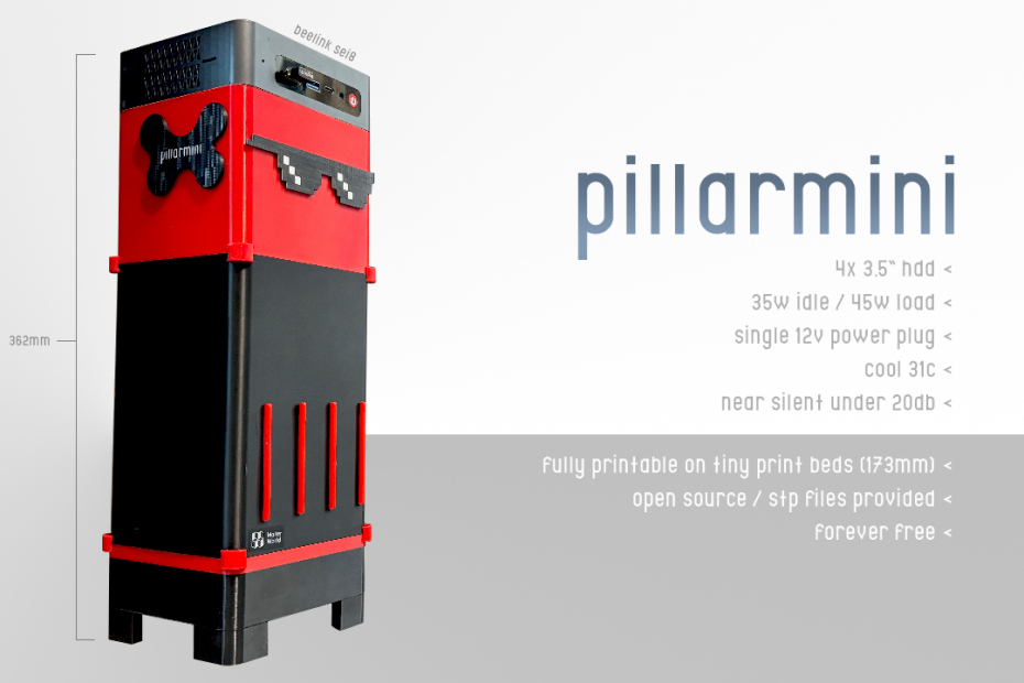
I consider Mini-ITX not aggressive enough for power savings, no matter the processor dropped in. Thus, a SOC (system on a chip) solution is required. Laptops and Mini PCs have their processor baked on, and have a far lower TDP than any desktop variant. Please note, the beelink SEI8 that I used I happened to have on hand. Obviously a more universal ring needs to be made to accept more and more mini-pc’s.
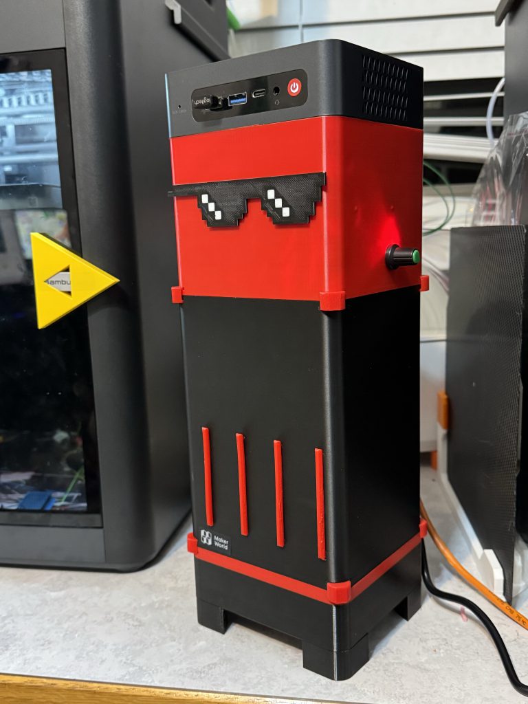
The Build.
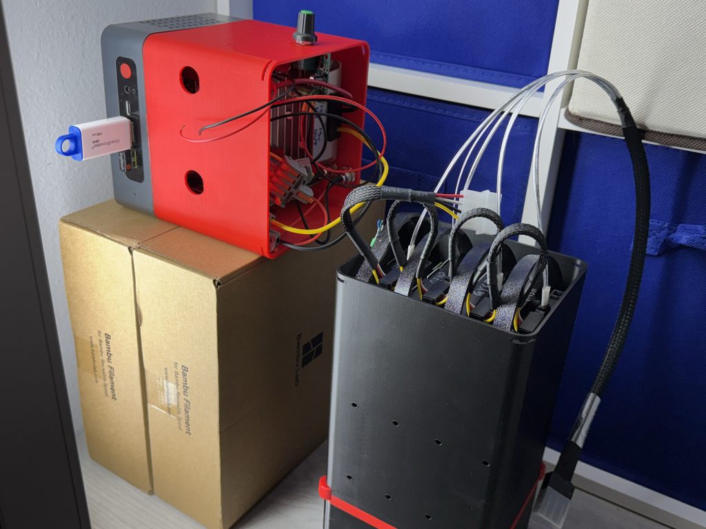
In summary, this build is simply this:
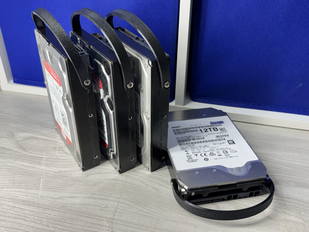
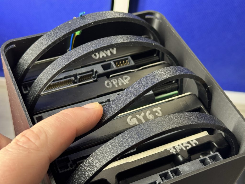
- A mini-pc in charge of 4 hard drives via M.2 to PCIEx4 to SAS card to 4 SATA cables, and a quiet, economical means to power it all properly.
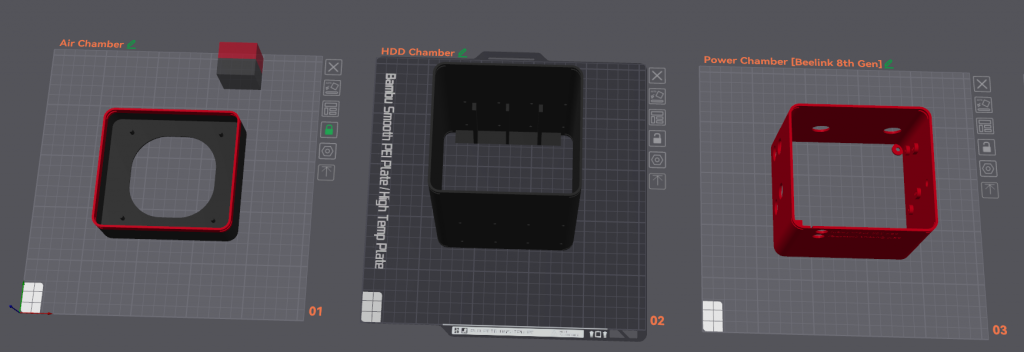
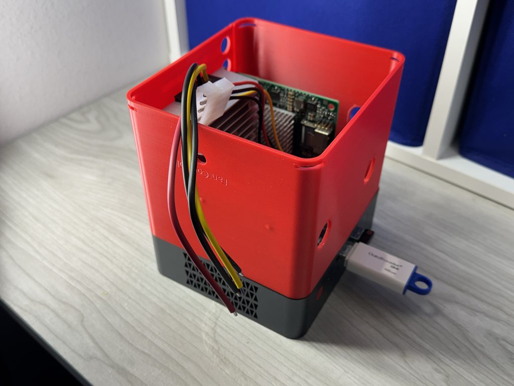
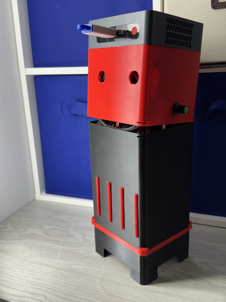
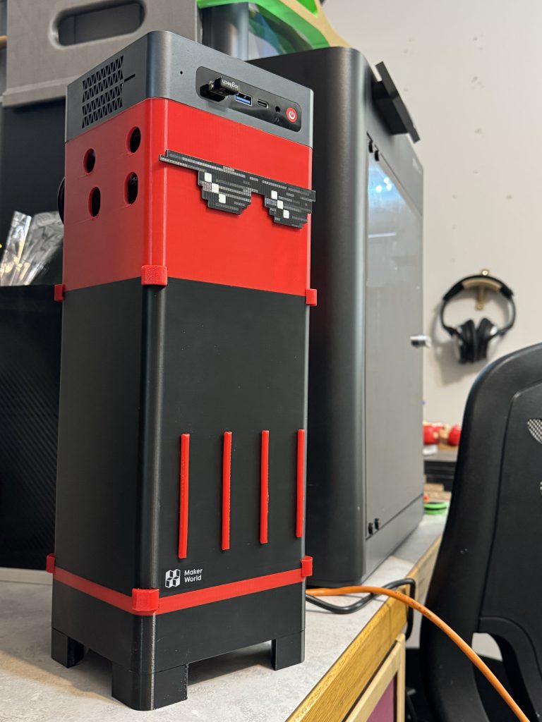
The Build consists of 3 main chassis pieces (and if you’ve seen the instructions for ANY other DIY 3D Printed NAS, you’re probably already salivating at the simplicity): The air chamber, hard drive chamber, and power chamber.
This particular power chamber piece is specifically tailored to the beelink SEI8, an 8th generation intel beelink i5 machine I had on hand — however, we’re posting this to makerworld under a creative commons license that allows pretty much anything, so, make an adapter ring to accommodate whatever mini-pc you’re rocking, and lets get printing! (Heck I’ll make a few adapter rings if there’s lots of demand for a specific model — lets get some N100 machines with 2.5GBe in here!)
Cost.
I’m personally installing Xpenology on here, so I’m comparing this build cost to a 4-bay synology [diskless] directly:
| Specification | Synology DiskStation DS423 | Synology DiskStation DS418 | Synology DiskStation DS420j |
|---|---|---|---|
| Processor | Realtek RTD1619B | Realtek RTD1296 | Realtek RTD1296 |
| CPU Cores | Quad-core 1.7 GHz | Quad-core 1.4 GHz | Quad-core 1.4 GHz |
| Memory | 2 GB DDR4 | 2 GB DDR4 | 1 GB DDR4 |
| Drive Bays | 4 | 4 | 4 |
| Max Capacity | 64 TB | 64 TB | 64 TB |
| Network Ports | 2 x 1GbE | 2 x 1GbE | 1 x 1GbE |
| USB Ports | 2 x USB 3.0 | 2 x USB 3.0 | 2 x USB 3.0 |
| TDP | 5 watts | 6 watts | 6 watts |
| Price (at the time) | $503.99 ???? | $699.99 ???? | $449.99 ???? |
The beelink SEI8 is what I had laying around. Despite 28w TDP, it idles much lower than that. I’d love to build some N100 builds in the future to compete (6w TDP).
More importantly though, Synology post 2020 has gotten completely out of control in their pricing. Even their 2-bay offerings are way too expensive:
| Specification | Synology DiskStation DS223j | Synology DiskStation DS223 | Synology DiskStation DS224+ |
|---|---|---|---|
| Processor | Realtek RTD1619B | Realtek RTD1619B | Intel Celeron J4125 |
| CPU Cores | Quad-core 1.7 GHz | Quad-core 1.7 GHz | Quad-core 2.0 GHz (burst up to 2.7 GHz) |
| Memory | 2 GB DDR4 | 2 GB DDR4 | 2 GB DDR4 (expandable up to 6 GB) |
| Drive Bays | 2 | 2 | 2 |
| Max Capacity | 32 TB | 32 TB | 32 TB |
| Network Ports | 1 x 1GbE | 1 x 1GbE | 2 x 1GbE |
| USB Ports | 2 x USB 3.2 Gen 1 | 2 x USB 3.2 Gen 1 | 2 x USB 3.2 Gen 1 |
| TDP | 5 watts | 5 watts | 10 watts |
| Price | $190 | $309 | $449.99 |
So what about this build?
| Specification | Beelink SEI8 |
|---|---|
| Processor | Intel Core i5-8259U |
| CPU Cores | Quad-core 2.3 GHz (up to 3.8 GHz) |
| Memory | 16 GB DDR4 (upgradable to 32 GB) |
| Drive Bays | 4 (with 9211-4i SAS card) |
| Max Capacity | 64 TB |
| Network Ports | WiFi 5, Bluetooth 5.0 |
| USB Ports | 4 x USB 3.0, 2 x USB 2.0 |
| TDP | 28 watts |
Obviously, your build may vary, but, basically, you just need a mini pc with at least one USB port, and one M.2 2280 slot. That’s… probably almost everything from Intel 6th generation onwards, honestly.
Even some of the most power efficient desktop processors you could drop into a mini-itx case (i5-12400T) is $200 by itself, and has a TDP of 35 watts. Then you have to buy a motherboard on top of that… etc. Oof.
Here’s the Build Sheet Purchase List.
Don’t worry there’s no affiliate links cause I hate money or something.
| Description | URL | Qty | Unit price | Total price |
| 5.5 x 2.5 MM DC Power Jack Socket | Link | 1 | $8.00 | $8.00 |
| 1 ft 5.5mm x 2.5mm 90 Degree Barrel Adapter | Link | 1 | $8.00 | $8.00 |
| 12v to 19v Step Up Voltage Regulator [5A] | Link | 1 | $18.00 | $18.00 |
| 12v 10A Power Supply [PC is 3A, Drives are 4A] | Link | 1 | $18.00 | $18.00 |
| 4-pin MOLEX Male to 4X 15-pin SATA | Link | 1 | $6.49 | $6.49 |
| 12V/24V to 5V 15A Step Down Converter | Link | 1 | $10.00 | $10.00 |
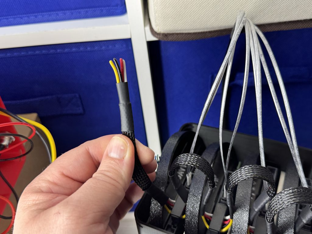
| SAS to SATA Breakout Cable | Link | 1 | $8.00 | $8.00 |
| M.2 NGFF Adapter (comes with funny 12v 4 pin adapter) | Link | 1 | $8.54 | $8.54 |
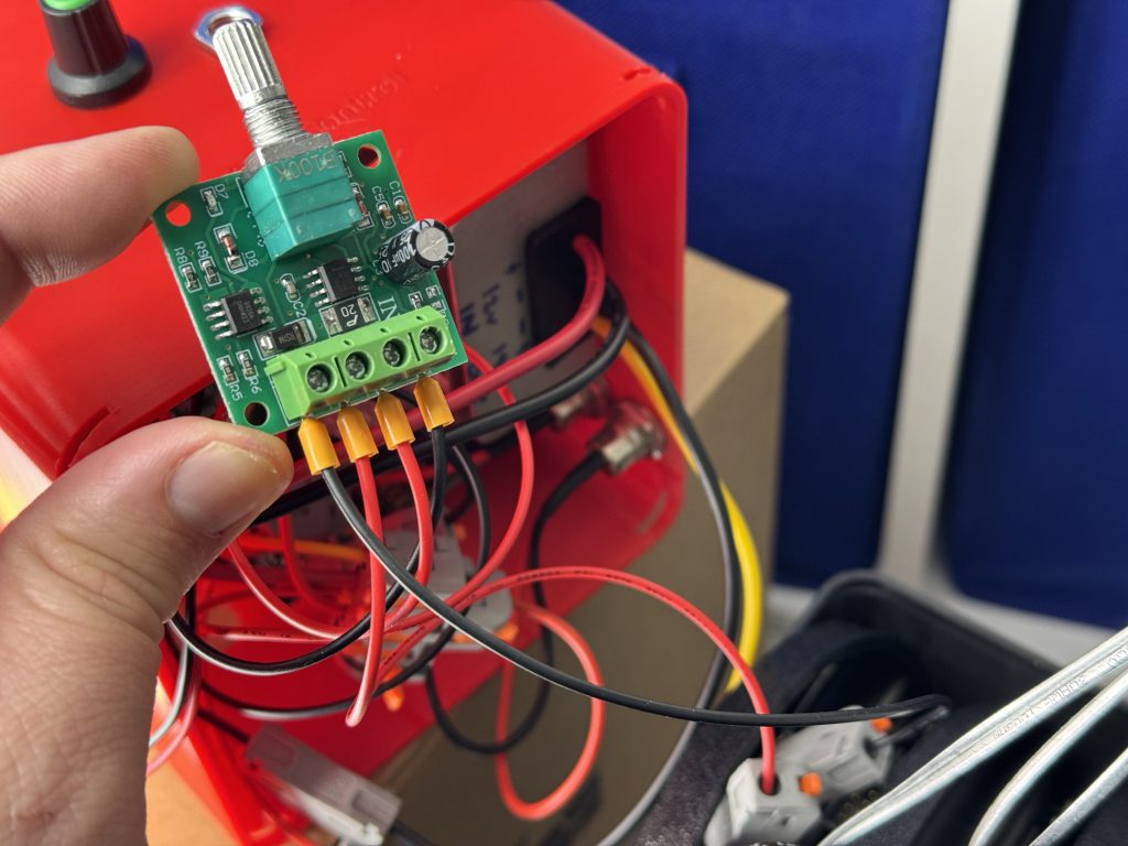
| DC Motor Speed Controller (Fan controller) | Link | 1 | $6.99 | $6.99 |
| 32Pcs Lever Wire Connectors (For no-solder approach) | Link | 1 | $14.98 | $14.98 |
| 92mm Fan | Whatever | 1 | $10.00 | $10.00 |
| SAS Card for 4 Drives (9211-4i with IT firmware, short version; H1110) | Link | 1 | $20.00 | $20.00 |
| A small amount of stranded wire. Steal it from a dead charging cable, whatever. | $0.00 | |||
| Notes: If links go dead, just google the description and check the images to ensure its the same. | Subtotal | $137.00 | ||
| Adjustments | $0.00 | |||
| Pretax | $137.00 | |||
And of course, your Mini-PC. You can get a 7th generation Intel NUC without power cord on ebay for $60 (we wont need the manufacturer cable). That would over-qualify, and keep your total DIY 4-bay synology cost at under $200.
If your mini PC doesn’t use a standard 5.5 x 2.5 barrel connection (and most do), adjust purchase list accordingly.
Instructions.
Don’t look at the scroll bar on the right. This article is deceptively long because I took pictures of every frigg’n step so even a noob that got their 3D printer yesterday can put this all together. Especially the electrical connections. Those are step by step. No soldering required. All easy lever-lock nuts.
Download the parts for free as a .3MF file from makerworld here. The order is best followed in the manner described below:
Step 1: The Air Chamber.
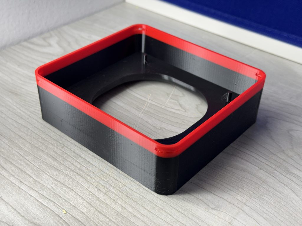
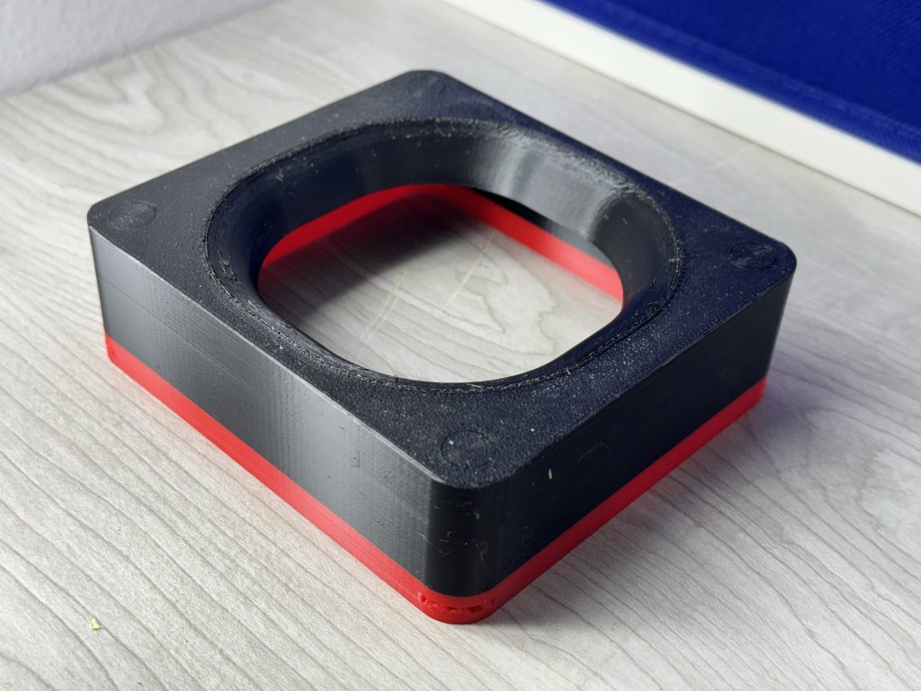

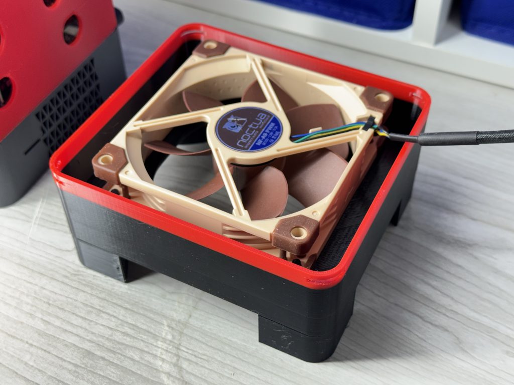
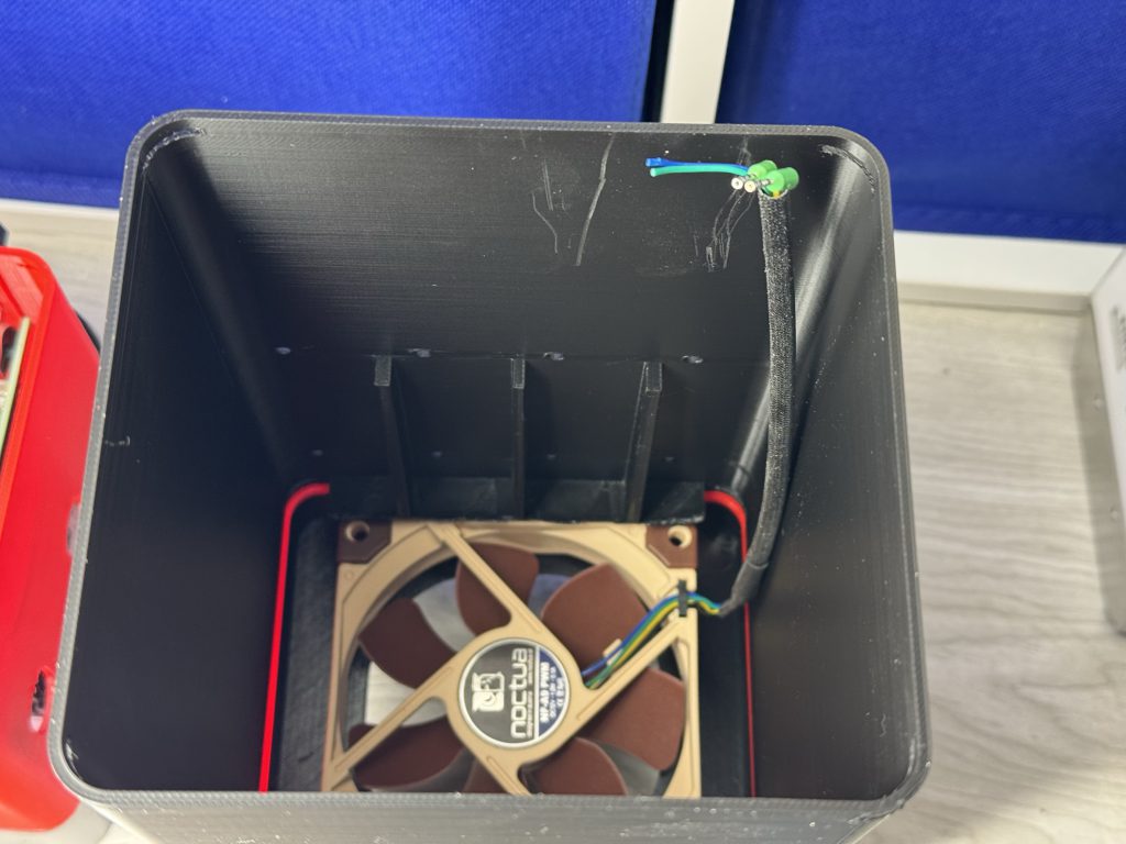
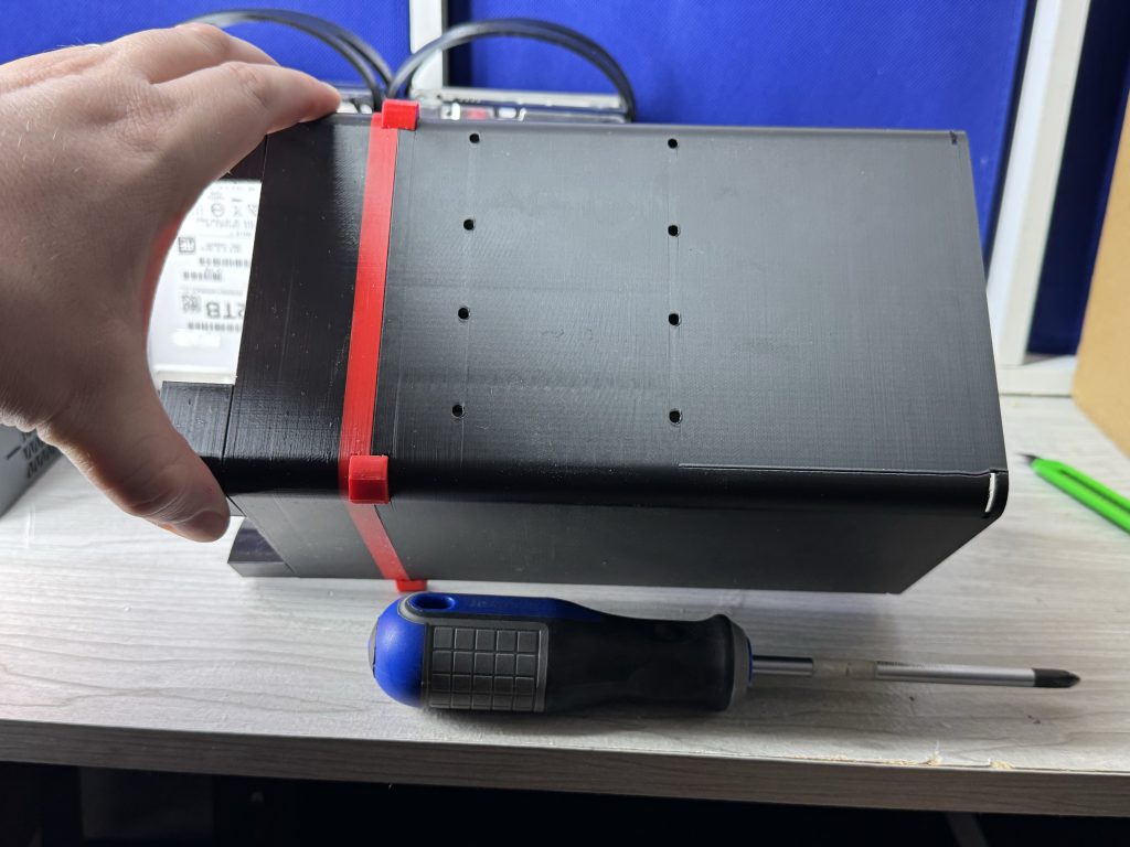
The pillarmini doesn’t use a backplane to keep things tight. Future builds such as PillarPlus (8-bay) and PillarMax (12-bay) likely will.
Congrats, you’re nearly done! 😀
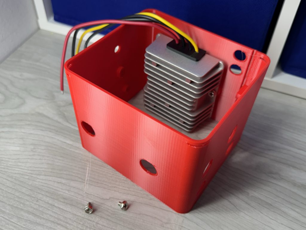
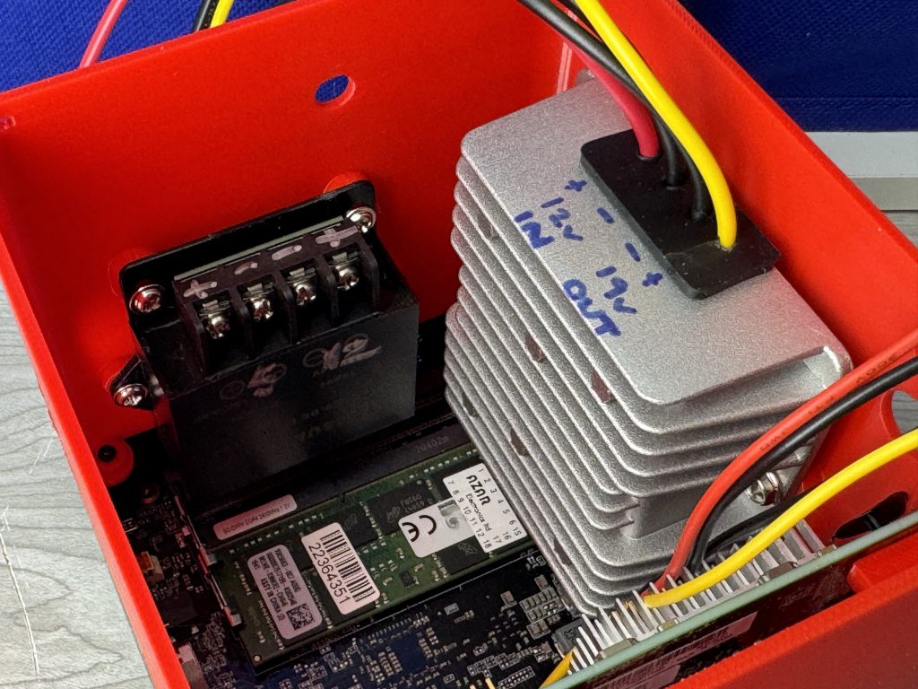
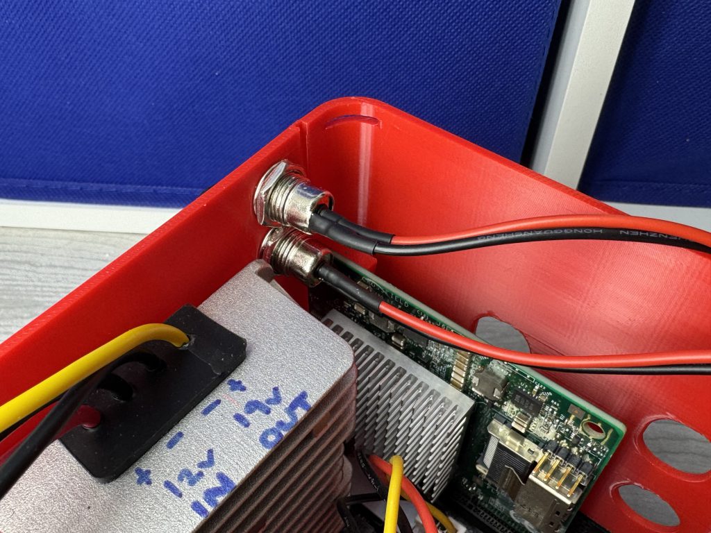
An up-stepper is something that takes a specific voltage (usually lower, like 12V for this example) and pushes it higher with a series of capacitors, and outputs 19V; Only 1 thing in our build uses 19V; The Mini-PC itself. This allows us to just use a single power port for the entire build.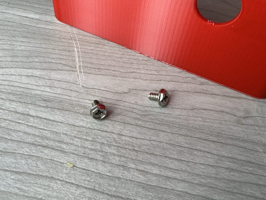
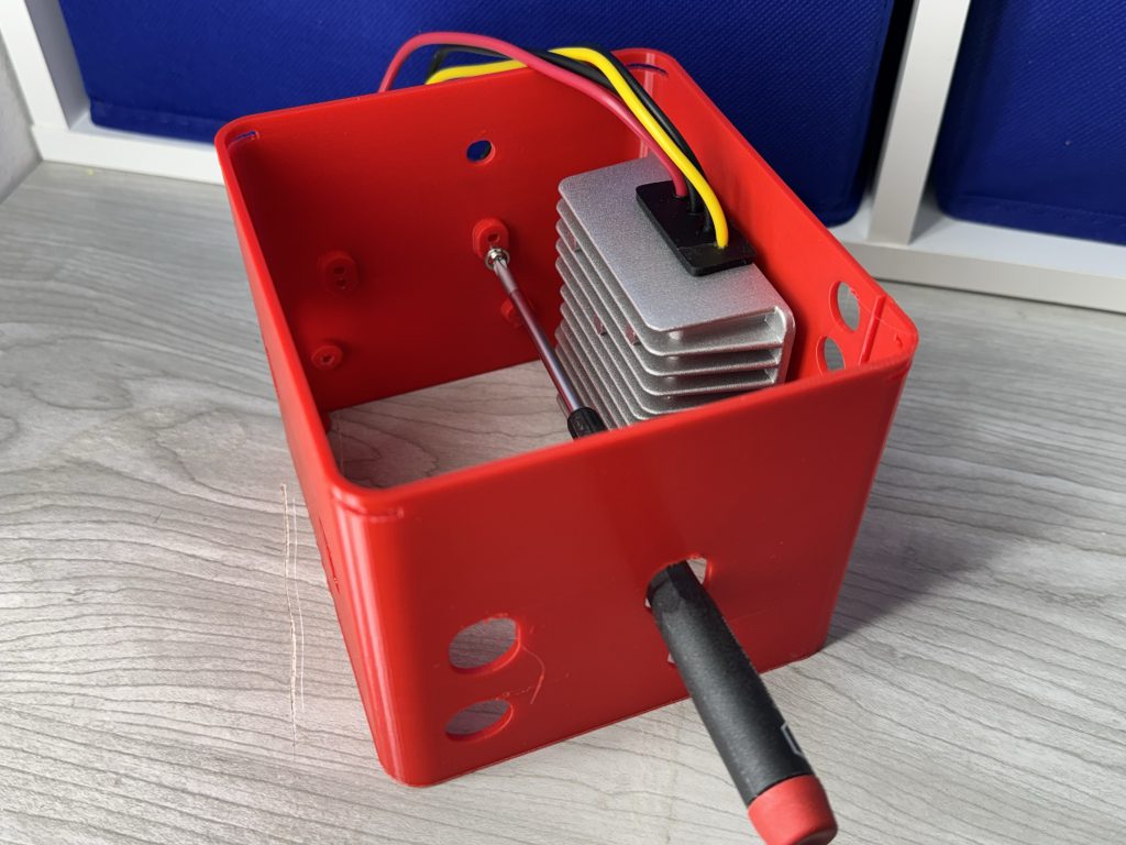
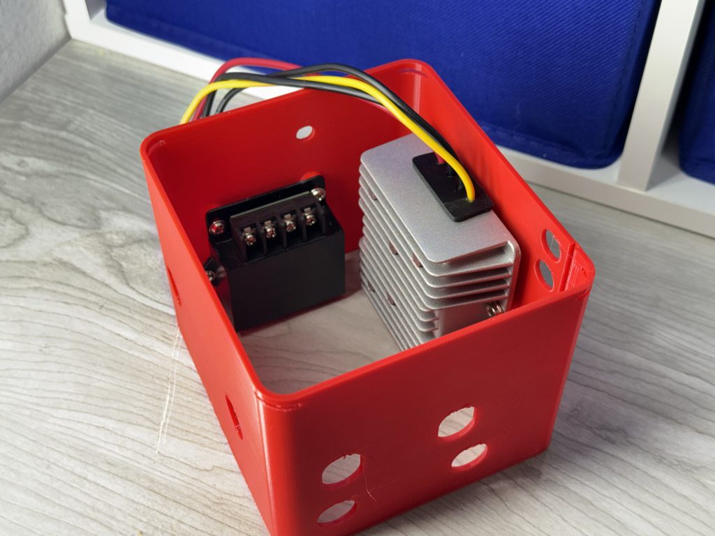
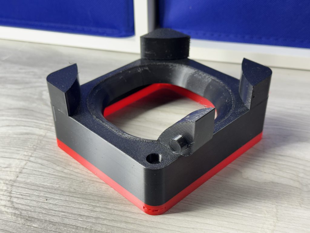
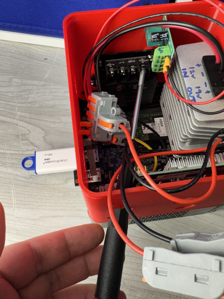
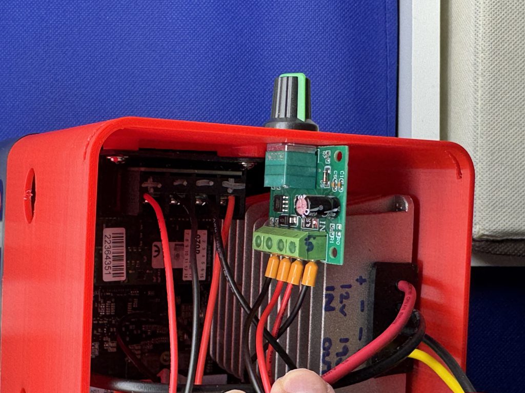
Mount the 5V downstepper. Note the orientation. (Loosen the screw terminals a bit since… its easier doing that this early.
A downstepper is something that takes a voltage and makes it smaller, IE: 12V to 5V in this example; The hard drives use both 12V and 5V, so we can get the 5V from here in this setup.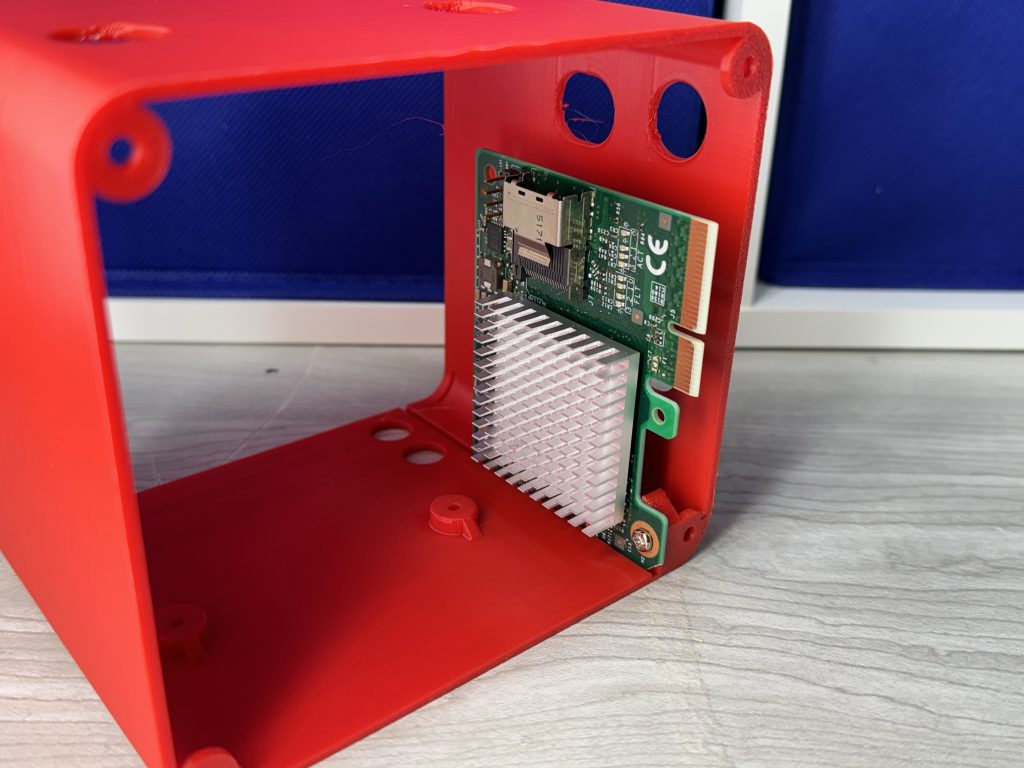
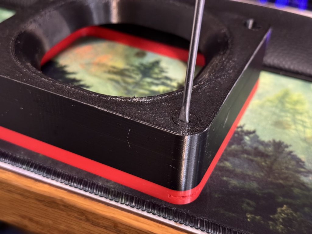
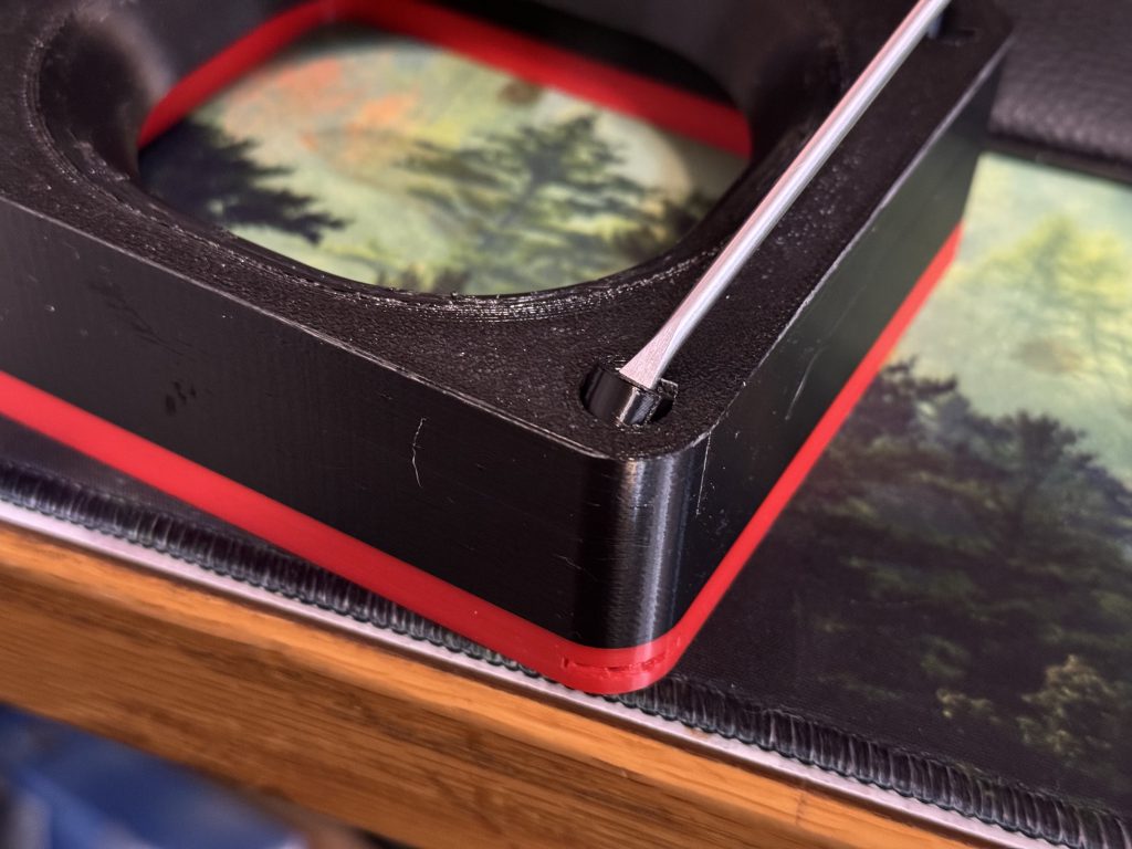
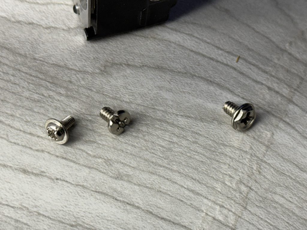
Only 1 screw is used at the bottom here, while the other hole uses a press-fit TPU dowel (on account there isn’t a good way to use a screwdriver for it). I didn’t realize it before, but plug your SAS Cable in from the hard drive chamber prior to mounting to avoid a more difficult later (feel free to temporarily unplug the SATA ports from the drives – easy to put back in a bit).
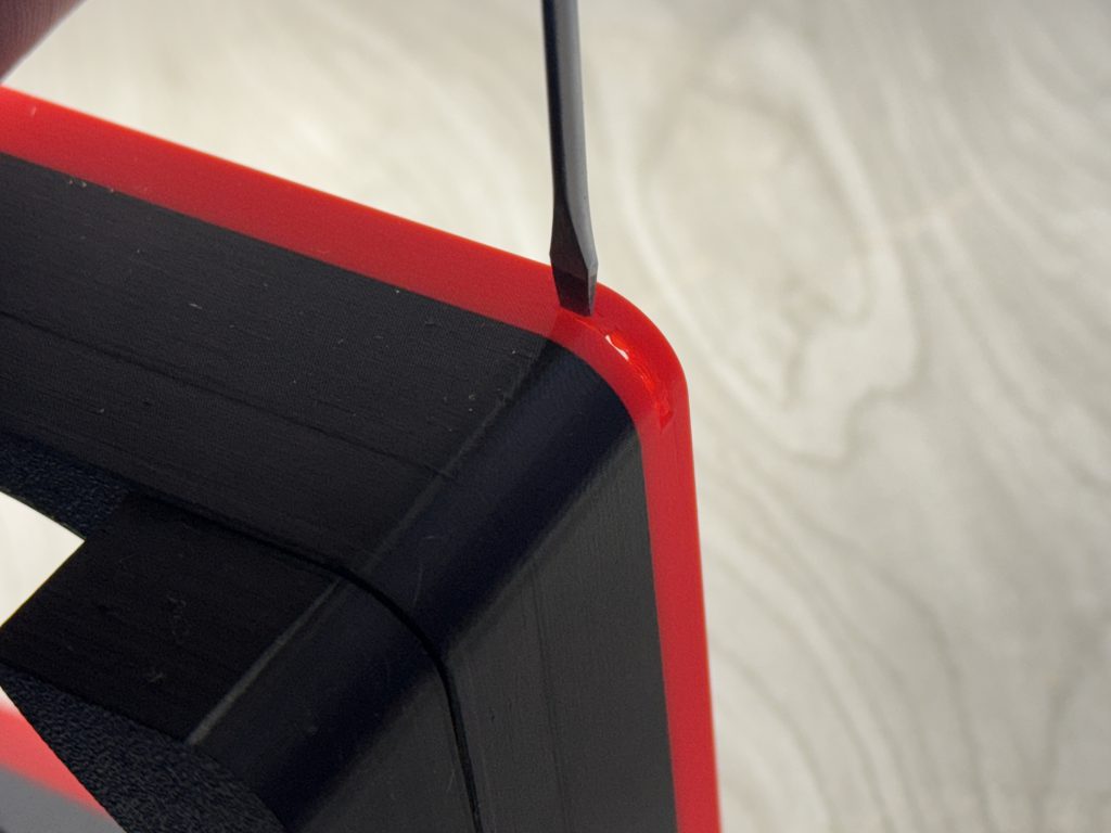
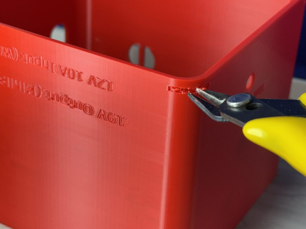
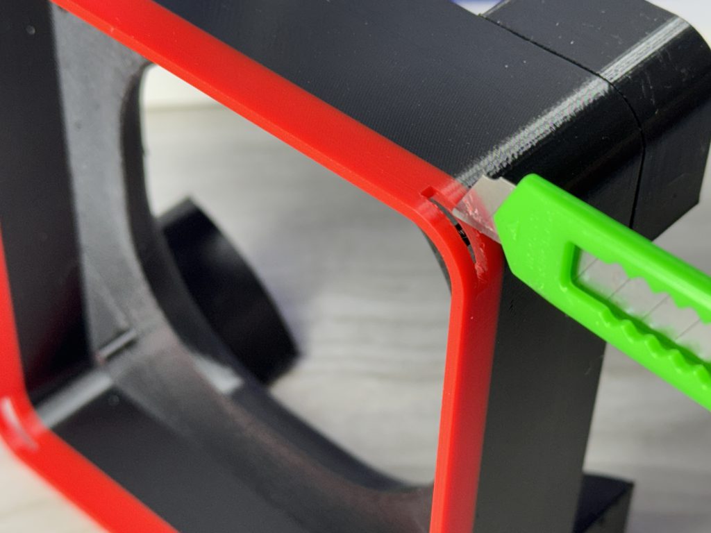
Please note that I definitely had to snip a tiny bit off the corner for this to sit flush into the Beelink SEI8 – you likely wont have to. If you can’t get yours to sit flush in your mini-pc, I’ll be making an alternative power chamber soon that will mount a PCIE x4 extension riser cable to the wall so any mini-pc set up should work.
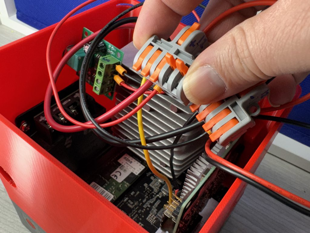
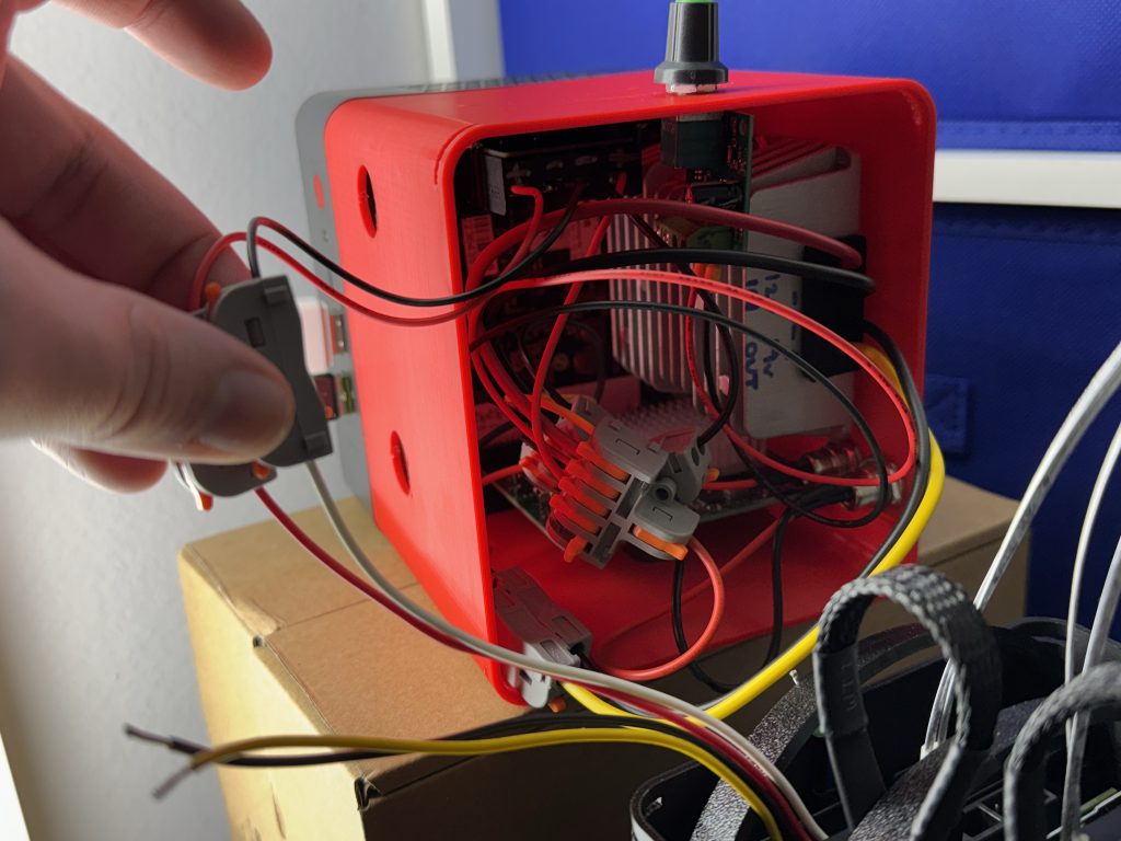
Electrical.
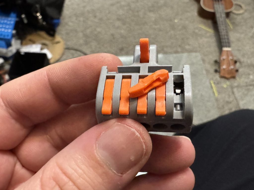
I promise I’ll make this part nice and painless. We use lever lock nuts on the entire thing and its easy.
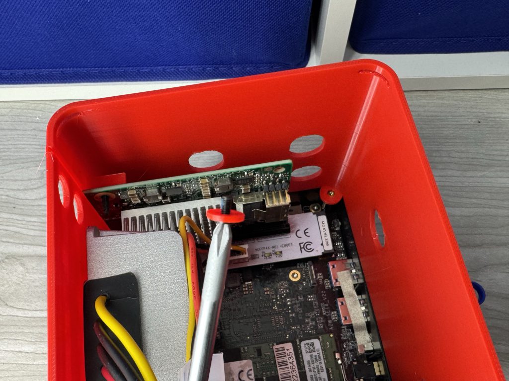
The one behind the SAS card gave me the game of ‘operation’ flashbacks. You got this.
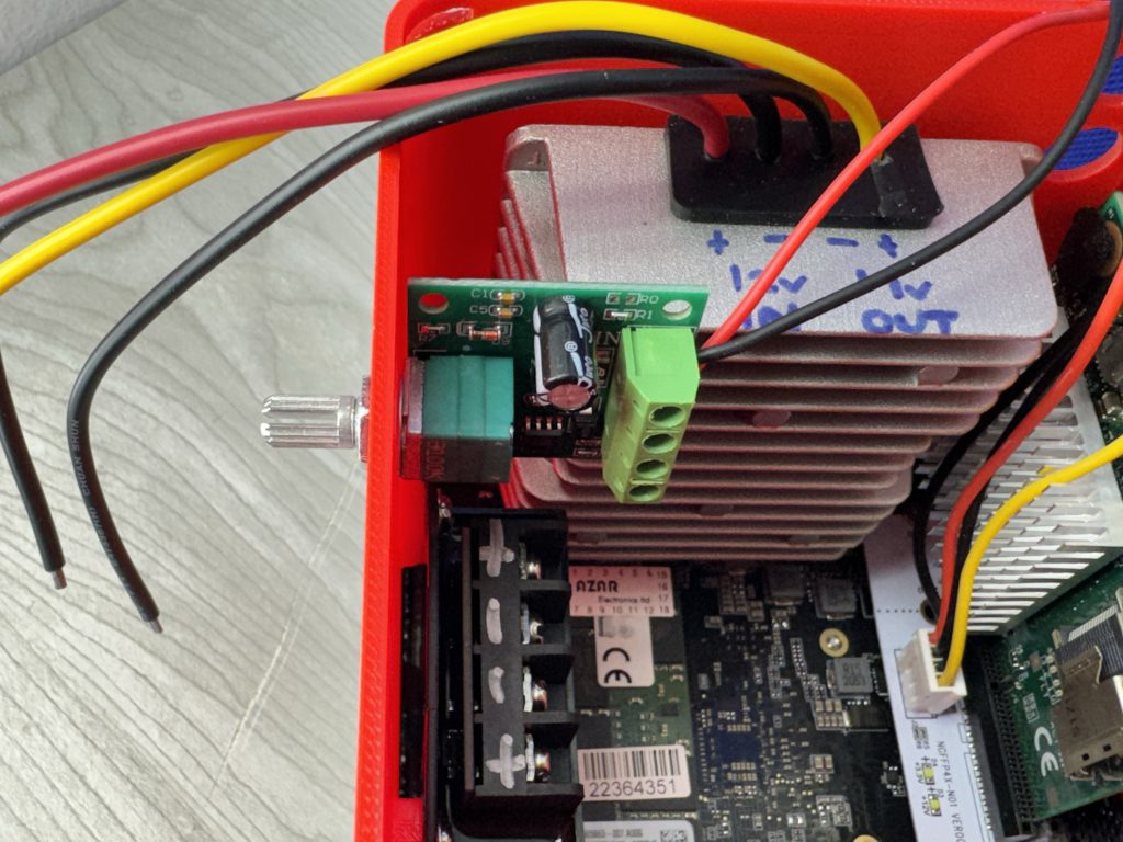

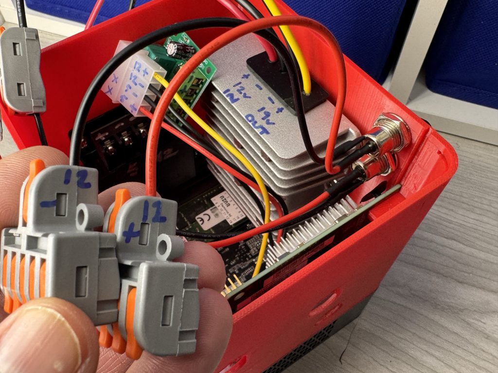
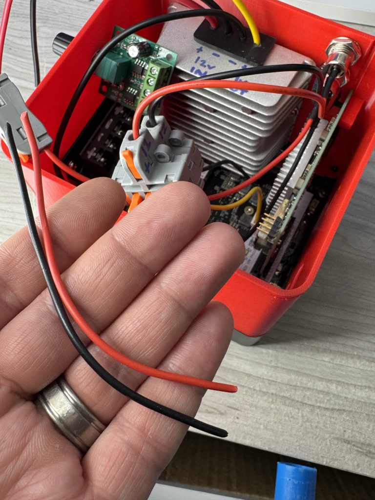
We need to spread 12V to 5 different locations in the box:
- The 19V upstepper needs to turn 12V into 19V, so it needs one.
- The 5V downstepper needs to turn 12V into 5V, so it needs one.
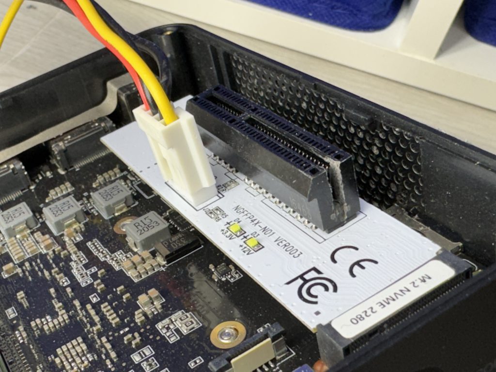
- The M.2 PCIe adapter needs 12V, so it needs one.
- Your fan at the bottom of the chassis uses 12V, so it needs one.
- And lastly, your hard drives all need 12V via that molex to 4x sata power adapter.
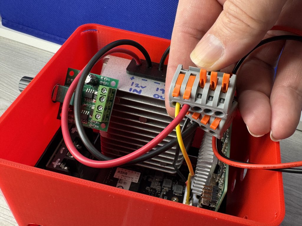
We need to spread 5V to only one location in the box:
- Your hard drives use a combination of 12V (to spin the drives) and 5V (to power the electronics like the controller board and other circuitry for read and write).
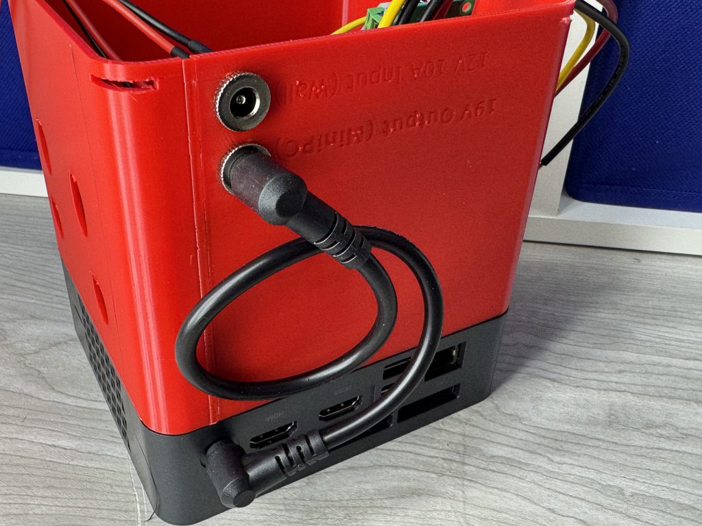
We need to spread 19V to only one location in the box:
- Your Mini-PC’s power plug port.
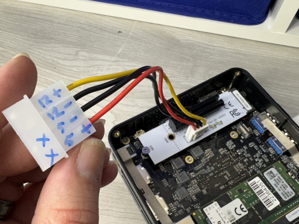
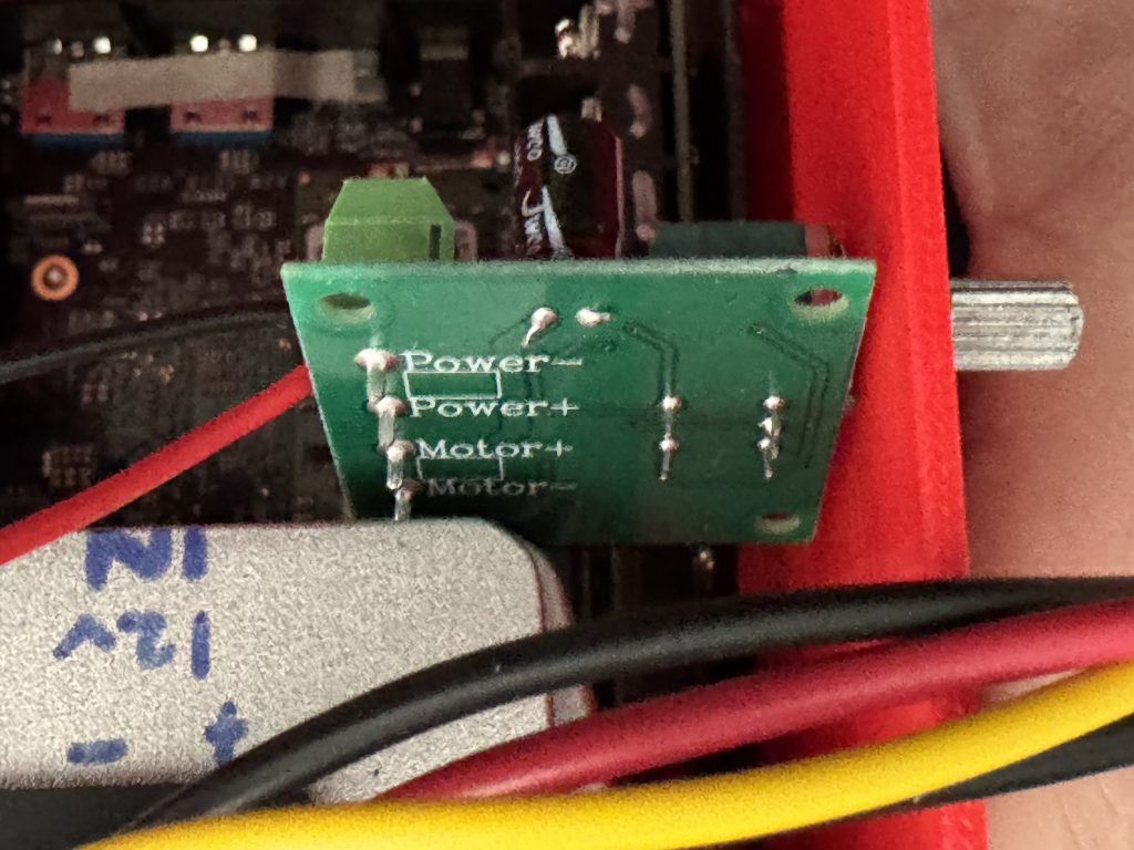
That’s it. You now have your mission set in front of you. Simplistically, every connection will have a “+” and a “-” (because electricity works by sending power through something in a loop; Goes in, goes out).
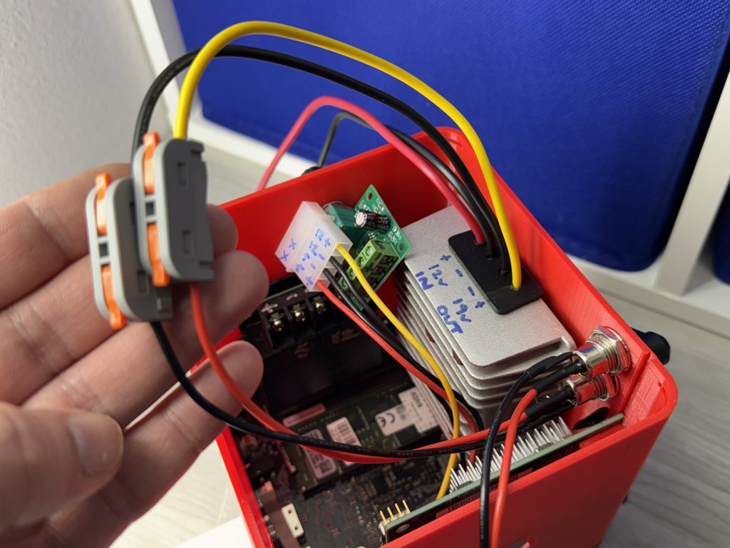
Next lets hook up all the 12V items.
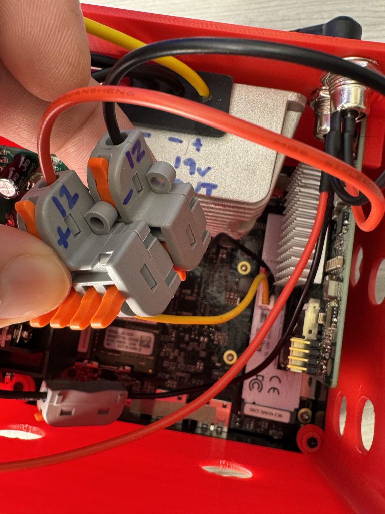
Also connect your black to the 12V- lever lock from your M.2 adapter.
Here’s your progress:
- The 19V upstepper needs to turn 12V into 19V, so it needs one.
- The 5V downstepper needs to turn 12V into 5V, so it needs one.
- ??? The M.2 PCIe adapter needs 12V, so it needs one.
- Your fan at the bottom of the chassis uses 12V, so it needs one.
- And lastly, your hard drives all need 12V via that molex to 4x sata power adapter.
Next, plug in the Red 12V+ to your 12V+ lever lock, and the black 12V- to the 12V- lever lock.
Here’s your progress:
- ??? The 19V upstepper needs to turn 12V into 19V, so it needs one.
- The 5V downstepper needs to turn 12V into 5V, so it needs one.
- ??? The M.2 PCIe adapter needs 12V, so it needs one.
- Your fan at the bottom of the chassis uses 12V, so it needs one.
- And lastly, your hard drives all need 12V via that molex to 4x sata power adapter.
Here’s your progress:
- ??? The 19V upstepper needs to turn 12V into 19V, so it needs one.
- The 5V downstepper needs to turn 12V into 5V, so it needs one.
- ??? The M.2 PCIe adapter needs 12V, so it needs one.
- ??? Your fan at the bottom of the chassis uses 12V, so it needs one.
- And lastly, your hard drives all need 12V via that molex to 4x sata power adapter.
Here’s your progress:
- ??? The 19V upstepper needs to turn 12V into 19V, so it needs one.
- ??? The 5V downstepper needs to turn 12V into 5V, so it needs one.
- ??? The M.2 PCIe adapter needs 12V, so it needs one.
- ??? Your fan at the bottom of the chassis uses 12V, so it needs one.
- And lastly, your hard drives all need 12V via that molex to 4x sata power adapter.

Here’s your progress:
- ??? The 19V upstepper needs to turn 12V into 19V, so it needs one.
- ??? The 5V downstepper needs to turn 12V into 5V, so it needs one.
- ??? The M.2 PCIe adapter needs 12V, so it needs one.
- ??? Your fan at the bottom of the chassis uses 12V, so it needs one.
- ??? And lastly, your hard drives all need 12V via that molex to 4x sata power adapter.
Now… onto whats left: Oh, right, your fan. That’s 12V. Forgot to connect to your actual fan:
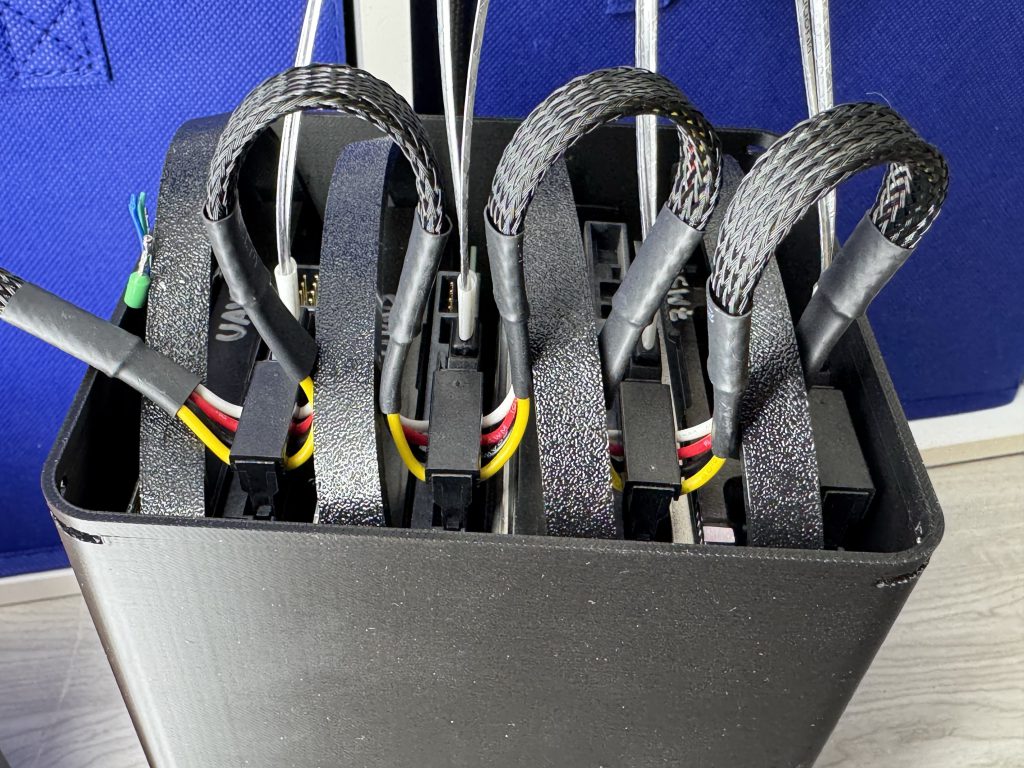
Finally, the 5V for your drives.
Cabling is coming from wiring I found around the house; Dead usb charging cords, extension cables etc. As long as it isn’t thinner than 22awg (it’ll typically say in really small text on the wire) you’re good.
Tested?
I’m serious go test it.
Nice. Good job, glad to hear its working. 😀
This is a good spot to talk about OUR SPONSOR! :D
It's nobody.
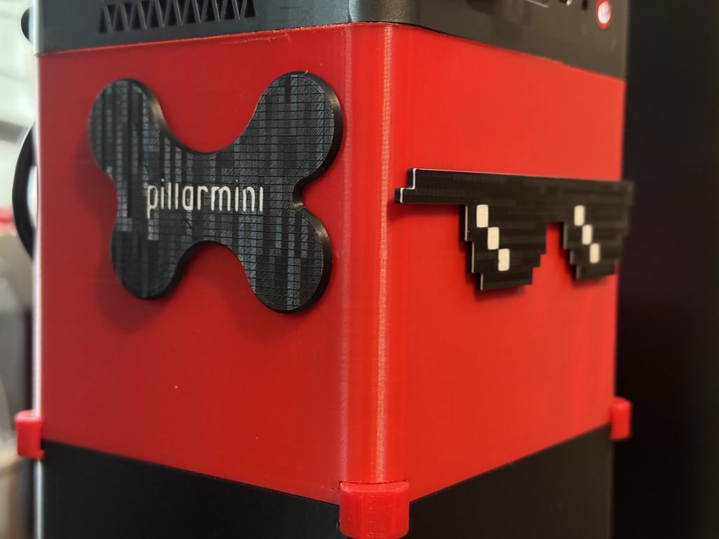
Anyway moving on to the finishing touches.Finishing touches.
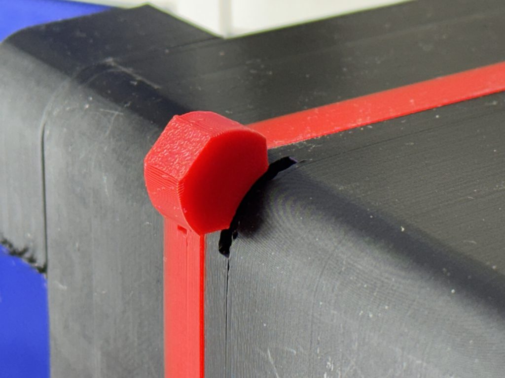
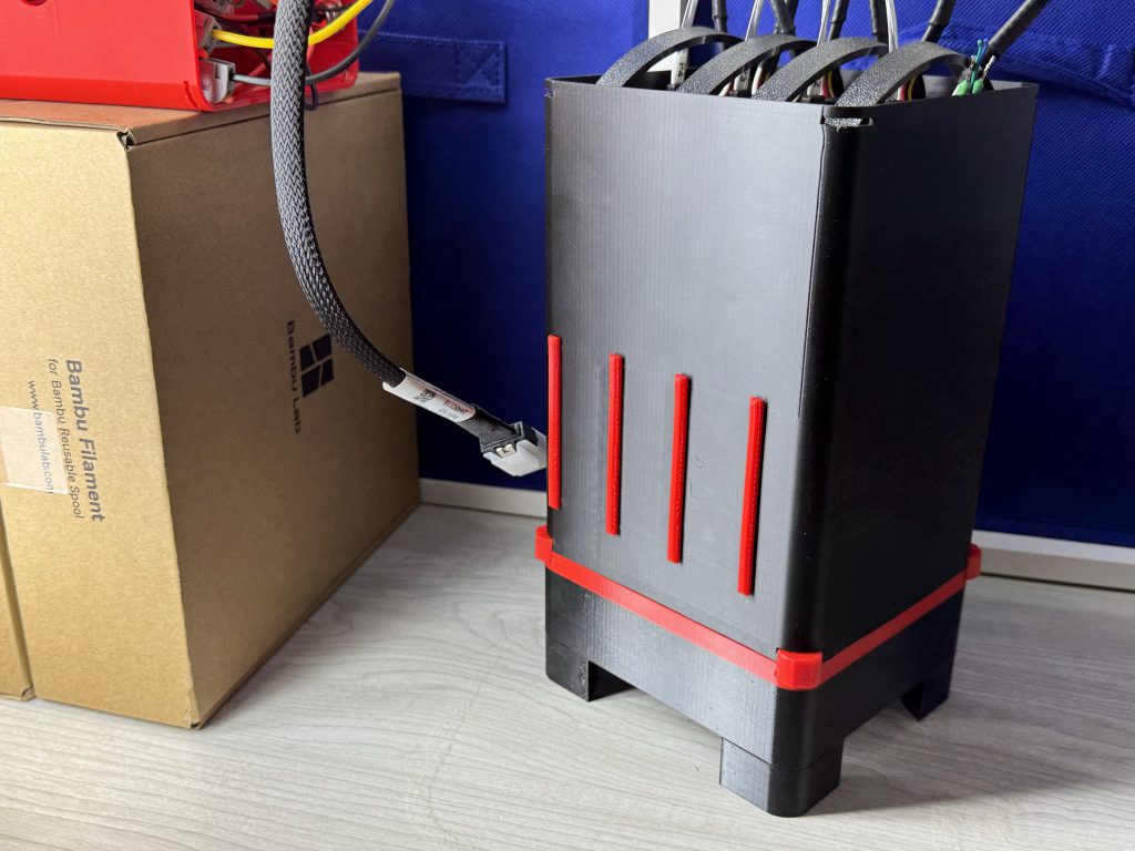
The strategic screwdriver holes are no longer required. These steps are optional, but, lets plug them in style. You can make your own too if you’d like! Be sure to share what you make as a remix on makerworld or similar – let everyone enjoy your style!
For the left 4 holes, I’d love to see what you come up with. I opted for just putting the PillarMini label on the side. 🙂 (Special thanks to my sister for letting me use her custom created font: alnor)
Worthy Notes (Power Usage, Temps, Noise, etc).
I can’t believe you’re still with me here. Sorry, I know its a long one.
Temps.
Temperatures, after being 95% done with a 20 hour extended S.M.A.R.T. test were:
- 35c while the fan was on the lowest non-off position.
- or, ~29-31c while the fan was in its highest position.
Power Usage
Idles at 35w. Goes to 45w under heavy loads.
More to come…
Of course, providing this gets received well enough, I have plans for larger setups, keeping the same goals all in mind.
- PillarPro [8-bay]
- PillarMax [12-bay]
- Pillar…ultra? […16-bay?]
Download:
You’ll find my creations here on Makerworld, for free of course.